This Quickstart provides you with the tools and know-how to install and work with the Linux Board Support Package (BSP) for the phyBOARD-Zeta. This Quickstart shows you how to do everything from installing the appropriate tools and source, to building custom kernels, to deploying the OS, to exercising the software and hardware. Additionally, gain access to the SOM and baseboard schematics for the phyBOARD-Zeta by registering at the following: http://phytec.com/support/registration/.
Requirements
The following system requirements are necessary to successfully complete this Quickstart. Deviations from these requirements may suffice, or may have other workarounds.
Hardware
- phyCORE-i.MX7 SOM (PCM-061.A4)
- phyBOARD-Zeta i.MX7 (PBA-C-09.A4)
- 2x 2x5 pin header to DB9 male connector
- Evaluation board PEB-EVAL-02 (optional)
- LCD Display Adapter with 7" capacitive display PEB-AV-02-TC (optional)
- Null-Modem RS232 DB9 cable (female to female)
- AC adapter with 2-pin phoenix connector supplying 5V DC, min. 2.5A
See release notes for supported SOM and carrier board versions.
Software
- A modern GNU/Linux Operating host system either natively or via a virtual machine:
- Ubuntu 14.04 LTS 64-bit recommended. Other distributions will likely work, please note that some setup information as well as OS-specific commands and paths may differ.
- If using a virtual machine, VMWare Workstation, VMWare Player, and VirtualBox are all viable solutions.
- Root access to your Linux Host PC. Some commands in the Quickstart will not work if you don’t have sudo access (ex. package installation, formatting SD card).
- At least 40-50GB free on target build partition.
- SD card reader operational under Linux.
- If you do not have SD card access under Linux then formatting, copying the bootloader, and mounting the root file system on an SD card will not be possible.
- Active Internet connection
Getting Started With Binary Images
This section is designed to get the board up-and-running with pre-built images.
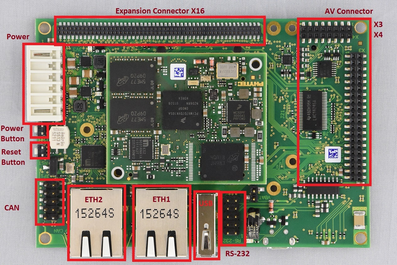
Connector Interfaces
Use the following as a reference for the connector interfaces on the phyBOARD-i.MX7 that will be used in this Quickstart.
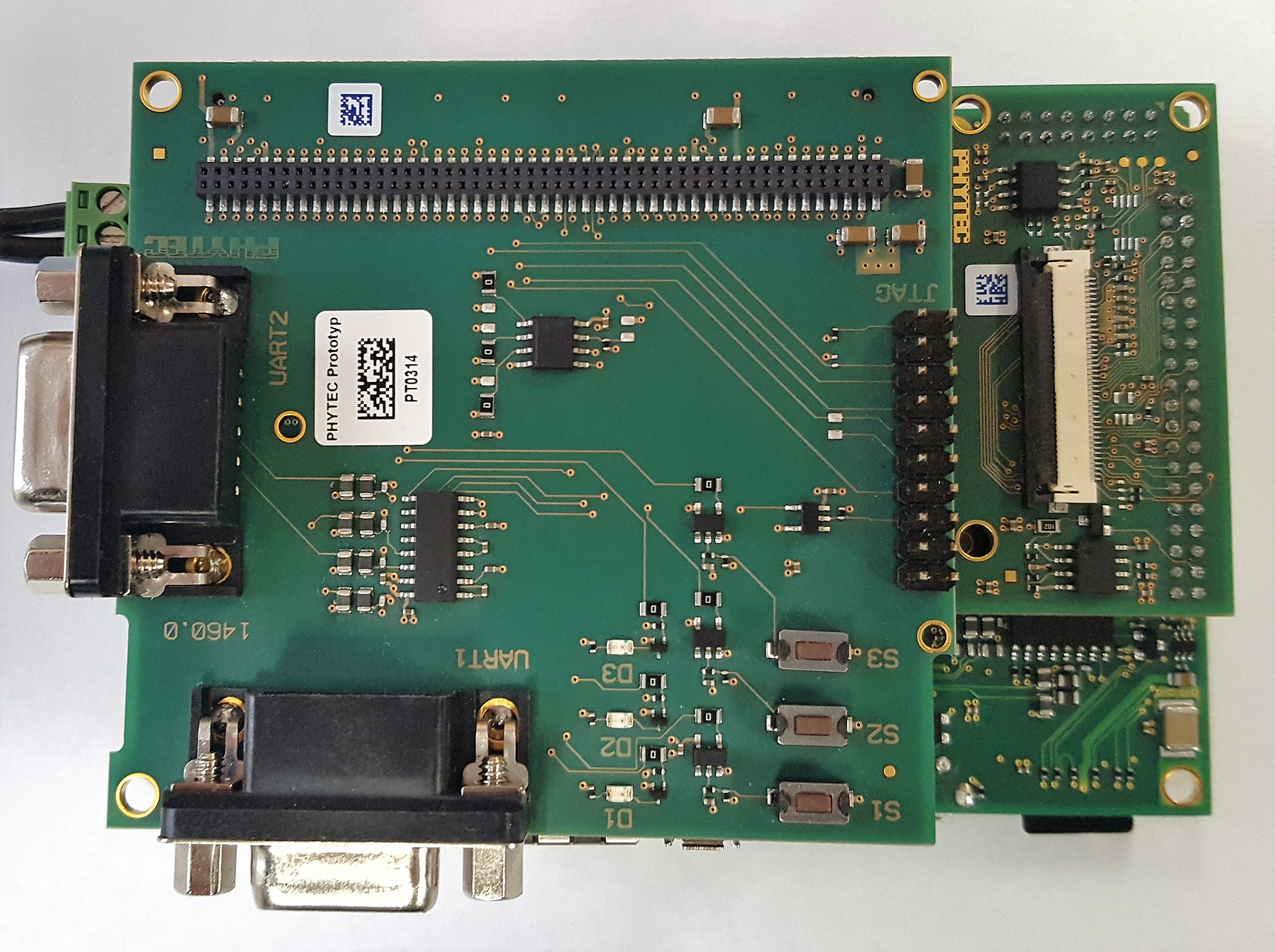
Expansion Boards
Use the following images as a reference when connecting any compatible PHYTEC expansion boards.

Booting the Pre-Built Images
The section was designed to show you how to boot the phyBOARD-Zeta with the pre-built images.
Download the binary images for BSP-Yocto-FSL-iMX7-ALPHA2 from PHYTEC's Artifactory.
Extract the tarball to your desired working directory:
tar -jxf BSP-Yocto-FSL-iMX7-ALPHA2.xml-b7.tar.bz2 -C <WORK_DIR>
Flash the SD card image to a micro SD card:
sudo dd if=fsl-image-gui-imx7d-phyboard-zeta.sdcard of=/dev/sd<SD partition> bs=1M && sync
For more information on formatting an SD card, see the Creating a Bootable SD Card section of the Quickstart.
If using the evaluation module PEB-EVAL-02, plug it into the expansion connector X16 on the carrier board.
- If using the LCD Display, connect the module PEB-AV-02-TC to the AV connectors X3 and X4.
Plug micro SD card into slot on underside of board.
Connect UART cable to the 5x2 pin header labelled "RS-232". This header requires an adapter as well as Null modem cable. When plugged in, the adapter cable should be oriented towards the USB and ethernet interfaces.
Start your favorite terminal software (such as Minicom or TeraTerm) on your host PC and configure it for 115200 baud, 8 data bits, no parity, and 1 stop bit (8n1) with no handshake
Connect 5V power supply to the 2-pin phoenix connector. Looking into the connector, the pin on the left is positive and the one next to it is negative.
- Press the "PWR" button (this may not be necessary if the battery has completely discharged). You will now start to see console output on your terminal window. If everything was done correctly the board should boot completely into Linux, arriving at a login prompt:
"Freescale i.MX Release Distro 4.1.15-1.2.0 imx7d-phyboard-zeta /dev/ttymxc4imx7d-phyboard-zeta login: root"
- The default login account is root with an empty password.
Troubleshooting
Not seeing output on the console?
- Make sure to press the power button on the carrier board. Unlike some other PHYTEC boards, the phyBOARD-i.MX7 does not get powered on simply by plugging in the power supply (this may not be necessary if the battery has completely discharged)
- Check that you have setup the terminal software correctly per step 8.
- Create a Bootable SD Card with the release images from the PHYTEC Artifactory, then configure the board to boot from SD/MMC (Selecting Boot Modes). After booting, you can restore your eMMC contents by following the Flashing Images to eMMC section.
Development Host Setup
Host Debian Packages
Yocto development requires certain packages to be installed. Run the following commands to ensure you have the packages installed:
sudo apt-get install gawk wget git-core diffstat unzip texinfo gcc-multilib build-essential chrpath socat libsdl1.2-dev xterm sed cvs subversion coreutils texi2html \
docbook-utils python-pysqlite2 help2man make gcc g++ desktop-file-utils libgl1-mesa-dev libglu1-mesa-dev mercurial autoconf automake groff curl lzop asciidoc u-boot-tools
The above is the recommended package installation for development on a Ubuntu 14.04 LTS Linux distribution. For a breakdown of the packages as well as a list of packages required for other Linux distributions, see the "Required Packages for the Host Development System" section in the Yocto Project Reference Manual: http://www.yoctoproject.org/docs/2.0.1/ref-manual/ref-manual.html#required-packages-for-the-host-development-system
Verify that the preferred shell for your Host PC is ''bash'' and not ''dash'':
sudo dpkg-reconfigure dash
# Respond "No" to the prompt asking "Install dash as /bin/sh?"
Repo Tool
Download and install the repo tool. This tool is used to obtain Yocto source from Git.
cd /opt
sudo mkdir bin

# /opt/ directory has root permission, change the permissions so your user account can access this folder. In the following replace <user> with your specific username
sudo chown -R <user>: bin

cd bin
curl http://commondatastorage.googleapis.com/git-repo-downloads/repo > ./repo
chmod a+x repo
Add the repo directory in your PATH, using export from the command line or permanently by including it in .bashrc:
export PATH=/opt/bin/:$PATH
Git Setup
If you have not yet configured your Git environment on this machine, please execute the following commands to set your user name and email address. See here for more information on getting started with Git.
git config --global user.email "your@email.com"
git config --global user.name "Your Name"
Server Setup (Optional)
TFTP
TFTP is a "trivial" file transfer protocol used to transfer individual files across a network. Setting up a TFTP server on your Linux Host PC will allow you to exchange files with the target board. Some examples where this will be advantageous include:
- Modifying and doing development on the Linux kernel. Barebox can be configured to remotely boot the kernel so you have access to the latest build without needing to continually reflash the target board.
- Updating images from the bootloader. Transferring files over a network in Barebox is an alternative to using an SD card which eliminates some time consuming steps such as formatting an SD card.
- Individual file transfer to the root fileystem. When Linux has been fully booted you may want to copy a specific file from your Host PC to the target board (images, application executables).
Install the TFTP server on your Host PC:
sudo apt-get install tftpd-hpa
Specify a folder where the files will reside on your Host PC by replacing the folder path for ''TFTP_DIRECTORY'' with whatever folder you wish to use as your TFTP file storage location, or leave the folder as the default.
sudo gedit /etc/default/tftpd-hpa
# /etc/default/tftpd-hpa
TFTP_USERNAME="tftp"
TFTP_DIRECTORY="/var/lib/tftpboot"
TFTP_ADDRESS="0.0.0.0:69"
TFTP_OPTIONS="--secure"
If you made any changes to the settings of the TFTP server, you need to restart it for them to take effect.
sudo restart tftpd-hpa
If you would like to grant every user on the system permission to place files in the TFTP directory, use the following command, replacing ''<TFTP_DIRECTORY>'' with your chosen location.
sudo chmod ugo+rwx <TFTP_DIRECTORY>
Files in the ''<TFTP_DIRECTORY>'' on your Host PC can now be accessed from another machine on the same network such as the target board by simply using the IP address of the Host PC. Take note of this IP address, in a typical wired connection this will be ''inet addr'' listed under ''eth0''.
ifconfig
NFS
A network filesystem (NFS) server gives other systems the ability to mount a filesystem stored on the Host PC and exported over the network. Setting up an NFS server on your Linux Host PC gives you access to the target boards root filesystem which will allow you to quickly test applications and evaluate different filesystem setups for the target board. That is, the root filesystem for the board will actually be located on the remote host Linux machine. This enables easy access and modifications to the root filesystem during development.
Install the NFS server on your Host PC:
sudo apt-get install nfs-kernel-server
Exported filesystems are designated in the "/etc/exports" file and allow you to choose both the directory to be exported and many settings for accessing the exports. Below is an example for exporting a folder called "nfs_export-ex" located in a user's home directory.
sudo gedit /etc/exports
# /etc/exports
/home/<user>/nfs_export-ex *(rw,sync,no_root_squash,no_subtree_check)
The options (rw, sync, no_root_squash, no_subtree_check) for this folder are essential in setting up the NFS export correctly. For more information on additional options, refer to the man page for 'exports'.
- rw enables: read and write access when the directory is mounted
- sync: tells the file-system to handle local access calls before remote access
- no_root_squash: allows root access when mounting the file-system
- no_subtree_check: reduces the number of checks the server must make to ensure that an exported sub-directory is within an exported tree and also enables access to root files in conjunction with no_root_squash
After modifying this file, in order to mount the directories as an NFS, you must force the NFS server to export all of the directories listed in "/etc/exports".
sudo /usr/sbin/exportfs -va
Samba
Samba servers are an excellent way to access a Linux file-system on a Windows machine via a network connection. Using a Samba server, it is quick and easy to transfer files between systems.
To install a Samba server, use the following command:
sudo apt-get install samba
Before the Samba share can be mounted on another machine it's necessary to modify the configuration file to allow write access and access to home directories. Start by editing the "/etc/samba/smb.conf" file.
sudo gedit /etc/samba/smb.conf
Inside this file there are four specific things that need to be uncommented (remove the ';' at the beginning of the line) to enable the sharing of home folders and write access. Below is the section that must be modified:
#======================= Share Definitions =======================
# Un-comment the following (and tweak the other settings below to suit)
# to enable the default home directory shares. This will share each
# user's home directory as \\server\username
;[homes]
; comment = Home Directories
; browseable = yes
# By default, the home directories are exported read-only. Change the
# next parameter to 'no' if you want to be able to write to them.
; read only = no
The outcomes after the changes are made follow:
#======================= Share Definitions =======================
# Un-comment the following (and tweak the other settings below to suit)
# to enable the default home directory shares. This will share each
# user's home directory as \\server\username
[homes]
comment = Home Directories
browseable = yes
# By default, the home directories are exported read-only. Change the
# next parameter to 'no' if you want to be able to write to them.
read only = no
It might also be necessary to change the ''workgroup'' line to match the workgroup for your machine.
To apply the changes, the next step is to restart all Samba-related processes.
sudo restart smbd
sudo restart nmbd
Lastly, each user needs to have a password enabled to be able to use the Samba server. There are no rules for this password. The simplest method for choosing this password is to make it the same as the UNIX user's password, but it is not a requirement. After typing in the command below, you will be prompted to enter the password for the specified user.
sudo smbpasswd -a <user>
As mentioned in the configuration file, the samba share can be connected by accessing "\\<host machine ip>\\<user>" by either mounting a network share or using Windows explorer to navigate to it.
Building the BSP from Source
Create a directory which will house your BSP development. In this example the BSP directory is /opt/PHYTEC_BSPs/. This is not a requirement and if another location is preferred (ex. ~/PHYTEC_BSPs) feel free to modify. We recommend using /opt over your HOME directory to avoid errors attributed to ~ syntax as well as the sudo requirement for the root filesystem and automation package building. We also recommend creating a package download directory (yocto_dl) separate from the yocto tree (yocto_imx7), as it makes resetting the build environment easier and subsequent build times much faster.
sudo mkdir /opt/PHYTEC_BSPs
cd /opt/

# /opt/ directory has root permission, change the permissions so your user account can access this folder. In the following replace <user> with your specific username
sudo chown -R <user>: PHYTEC_BSPs

cd PHYTEC_BSPs
mkdir yocto_imx7
mkdir yocto_dl
cd yocto_imx7
export YOCTO_DIR=`pwd`
At this point you will now be able to navigate to the Yocto directory using the $YOCTO_DIR environment variable.
Download the BSP Meta Layers
Download the manifest file for BSP-Yocto-FSL-iMX7-ALPHA2:
cd $YOCTO_DIR
repo init -u https://stash.phytec.com/scm/pub/manifests-phytec.git -b imx7 -m BSP-Yocto-FSL-iMX7-ALPHA2.xml
Download the Yocto meta layers specified in the manifest file:
repo sync
Start the Build
Run the Yocto build directory setup. The TEMPLATECONF variable is used to set the source of the local configuration files (conf/bblayers.conf and conf/local.conf), which are located in the meta-phytec layer:
cd $YOCTO_DIR
TEMPLATECONF=$YOCTO_DIR/sources/meta-phytec/conf MACHINE=imx7d-phyboard-zeta source sources/poky/oe-init-build-env build
Add the the new download directory to build/conf/local.conf:
DL_DIR ?= "/opt/PHYTEC_BSPs/yocto_dl"
Maximize build efficiency by modifying the BB_NUMBER_THREADS variable to suit your host development system. This sets the maximum number of tasks that BitBake should run in parallel. Also set the variable PARALLEL_MAKE to specify the number of threads that make can run. By default, these are set to 4 in build/conf/local.conf:
# Parallelism options - based on cpu count
BB_NUMBER_THREADS ?= "4"
PARALLEL_MAKE ?= "-j 4"
Accept Freescale EULA
To use Vivante GPU binaries in package 'gpu-viv-bin-mx6q' you need to accept the Freescale EULA at '/opt/yocto/yocto_fsl/sources/meta-fsl-arm/EULA'. Please read it and if you accept it, write the following in build/conf/local.conf:
ACCEPT_FSL_EULA = "1"
The setup is complete and you now have everything to complete a build. This BSP has been tested with the fsl-image-gui image. It is suggested that you start with this image to verify functionality before building other images. Alternate images are located in various meta layers at meta*/recipes*/images/*.bb. They can be found using the command bitbake-layers show-recipes "*-image*" in $YOCTO_DIR/build/.
The following will start a build from scratch including installation of the toolchain as well as the bootloader, Linux kernel, and root filesystem images.
cd $YOCTO_DIR/build
MACHINE=imx7d-phyboard-zeta bitbake fsl-image-gui
Built Images
All images generated by bitbake are deployed to $YOCTO_DIR/build/tmp/deploy/images/imx7d-phyboard-zeta:
- SD Image: fsl-image-gui-imx7d-phyboard-zeta.sdcard
- Bootloader: u-boot.imx
- Kernel: zImage
- Kernel device tree file: zImage-imx7d-phyboard-zeta.dtb
- Root Filesystem: fsl-image-gui-imx7d-phyboard-zeta.ext4
Source Locations:
- Kernel: $YOCTO_DIR/build/tmp/work/imx7d_phyboard_zeta-poky-linux-gnueabi/linux-phytec-fsl/4.1.15+git_BSP-Yocto-FSL-iMX7-ALPHA2-b25-r0/git/
- The device tree file to modify within the linux kernel source is: arch/arm/boot/dts/imx7d-phyboard-zeta.dtb and its dependencies
U-Boot:$YOCTO_DIR/build/tmp/work//imx7d_phyboard_zeta-poky-linux-gnueabi/u-boot-phytec/2015.04+git_BSP-Yocto-FSL-iMX7-ALPHA2-b25-r0/git/
Board file is located at: board/phytec/mx7d_phyboard/mx7d_phyboard.c
- Toolchain: $YOCTO_DIR/build/tmp/sysroots/x86_64-linux/usr/bin/arm-poky-linux-gnueabi/arm-poky-linux-gnueabi-
Build Time Optimizations
The build time will vary depending on the package selection and Host performance. Beyond the initial build, after making modifications to the BSP, a full build is not required. Use the following as a reference to take advantage of optimized build options and reduce the build time.
To rebuild Barebox:
bitbake u-boot-phytec -f -c compile && bitbake u-boot-phytec
To rebuild the Linux kernel:
bitbake linux-phytec-fsl -f -c compile && bitbake linux-phytec-fsl
The Yocto project's Bitbake User Manual provides useful information regarding build options: http://www.yoctoproject.org/docs/2.0.1/bitbake-user-manual/bitbake-user-manual.html
Customizing the BSP
We recommend you create your own layer and make changes to the existing BSP there. This will make it easier to update the BSP. Instructions and tips on creating your own layer are available here: http://www.yoctoproject.org/docs/2.0.1/dev-manual/dev-manual.html#creating-your-own-layer.
Appending Recipes
To modify an existing recipe in your own layer, use a bbappend file. The following is an example of modifying the u-boot-phytec_2015.04 recipe, u-boot-phytec_2015.04.bb, located at $YOCTO_DIR/sources/meta-phytec/recipes-bsp/u-boot/u-boot-phytec_2015.04.bb.
Create a recipes-bsp/barebox/ directory in your own meta-layer to place the bbappend file in. Make sure that the new file matches the .bb file name exactly. Alternatively, you may use % after the underscore in place of the specific version for portability with future versions of the recipe.
mkdir $YOCTO_DIR/sources/<YOUR_META_LAYER>/recipes-bsp/u-boot/
vim $YOCTO_DIR/sources/<YOUR_META_LAYER>/recipes-bsp/u-boot/u-boot-phytec_%.bbappend
For information on how to write a recipe, see chapter 5.3 of the Yocto Development Manual: http://www.yoctoproject.org/docs/2.0.1/dev-manual/dev-manual.html#understanding-recipe-syntax
Adding packages to the Build
There are various ways to add a package to the BSP. For example, packages and package groups can be added to image recipes. See the Yocto Development manual for how to customize an image: http://www.yoctoproject.org/docs/2.0.1/dev-manual/dev-manual.html#usingpoky-extend-customimage-imagefeatures.
The following instructions demonstrate how to add a package to the local build of the BSP. First, search for the corresponding recipe and which layer the recipe is in. This link is a useful tool for doing so: http://layers.openembedded.org/layerindex/branch/jethro/layers/.
If the package is in the meta-openembedded layer, the recipe is already available in your build tree. Add the following line to $YOCTO_DIR/build/conf/local.conf:
IMAGE_INSTALL_append = " <package>"
The leading whitespace between the " and the package name is necessary for the append command.
If you need to add a layer to the BSP, clone or extract it to the $YOCTO_DIR/sources/ directory. Then, modify $YOCTO_DIR/build/conf/bblayers.conf to include this new layer in BBLAYERS:
BBLAYERS += "${BSPDIR}/sources/<new_layer>"
Configuring the Kernel
The kernel configuration menu allows the user to adjust drivers and support included in a Linux Kernel build. run the following command from the build directory:
cd $YOCTO_DIR/build
bitbake linux-phytec-fsl -c menuconfig
Then rebuild the kernel:
bitbake linux-phytec-fsl -f -c compile && bitbake linux-phytec-fsl
To rebuild the root filesystem:
bitbake -f fsl-image-gui
Customizing the Devicetree
The device tree is a data structure for describing hardware, and is a way of separating machine specific information from the kernel. For information on the device tree concept, devicetree.org is a good source: http://devicetree.org/Device_Tree_Usage.
Device trees for PHYTEC products consist of a board DTS file, a SOM dtsi and a carrier board dtsi. The SOM dtsi includes the processor dtsi and contains definitions for all devices that are located on the SOM, such as eMMC flash. Peripherals whose signals are routed through the SOM but whose hardware is located on the carrier board are defined in the carrier board dtsi, such as SD/MMC. All of the peripherals in these files are enabled or disabled in imx7d-phyboard-zeta.dts.
The kernel source directory has very good documentation and examples on what bindings are supported for specific peripherals: Documentation/devicetree/bindings/.
Creating a Bootable SD Card
The process requires an SD card reader operational under Linux to format and access the Linux partition of the card. If you do not have SD card access under Linux then copying the bootloader and mounting the root filesystem on SD/MMC card will not be possible.
If using pre-built images provided by PHYTEC, the exact image names are listed in the instructions below. If you have built your own images, then the images are located in: $YOCTO_DIR/build/tmp/deploy/images/imx7d-phyboard-zeta/
- Determine the SD card device name
The SD card device name is of the form /dev/sd[b|c|d|e]. Run the following without and with the SD card connected:
ls /dev/sd*
The device that appeared on the call to ls with the SD card but not the call without is the SD card device.
Unmount all partitions of the SD card, using the SD card device name from Step 1:
umount /dev/sd[b|c|d|e]*
Load the sd-card image onto the SD card from the linux command line. This will format the appropriate partitions, as well as add U-Boot, the kernel image, and the root filesystem to the card:
sudo dd if=fsl-image-gui-imx7d-phyboard-zeta.sdcard of=/dev/sd[b|c|d|e] bs=1MB && sync
Once the SD card has been formatted, you may update the kernel, root filesystem, and u-boot individually as well:
Kernel
If modifying the kernel, remove the existing zImage and device tree binary files:
rm /media/Boot\ imx7-p/zImage
rm /media/Boot\ imx7-p/imx7d-phyboard-zeta.dtb
Load the new Linux kernel and device tree binary to the SD Card:
cp zImage /media/Boot\ imx7-p/; sync
cp zImage-imx7d-phyboard-zeta.dtb /media/Boot\ imx7-p/imx7d-phyboard-zeta.dtb; sync
Root Filesystem
If modifying the root filesystem, remove the existing:
sudo rm -rf /media/<rootfs partition>/*
Load the new filesystem to the SD Card:
sudo tar -jxf fsl-image-gui-imx7d-phyboard-zeta.tar.bz2 -C /media/<rootfs partition>/; sync
Bootloader
Flash u-boot to the SD card:
sudo dd if=u-boot.imx of=/dev/sd[b|c|d|e] bs=512 seek=2 conv=fsync
Boot Configurations
Selecting Boot Modes
The bootloader, one of the key software components included in the BSP, completes the required hardware initialization to download and run operating system images. The boot mode, selected from the S1 dipswitch on the underside of the carrier board, determines the location of the primary bootloader. Set the S1 dipswitch correspondingly:
SD Card
(4-bit SD1 interface)

eMMC
(8-bit SD3 interface)

Note that the U-Boot environment is configured to autodetect which mmc interface U-boot was booted from and boot the kernel and root file system from the same device. More information below.
Basic Settings
After application of power, approximately three seconds are allotted for the user to hit any key which will halt autoboot and enter U-Boot:
help is a useful tool in U-Boot to show available commands and usage.
Saving Configurations
After confirming the environment variables are correct, save them and continue on to the next section to set the correct kernel and root filesystem boot location:
saveenv
Boot Options
The target can be booted from on-board media or from a development host via network (Booting from network untested in BSP-Yocto-FSL-iMX7-ALPHA2). In our standard configuration, this BSP release loads the kernel and root filesystem from MMC if an SD card is inserted in the micro SD card slot. If no SD card is present, it will boot from eMMC.
Stand Alone SD/MMC Card Boot
This is the default boot configuration. Simply type the following:
boot
Stand-Alone eMMC Boot
By default, U-boot is configured to auto-detect if there is a device connected to interface mmc0, which corresponds to the SD card slot. If not, then it will boot from mmc1, which is eMMC. However, if you would like to boot from eMMC regardless of whether or not there is an SD card inserted, then disable auto-detection and set the mmc boot device to mmc1 by modifying the environment as follows:
=> setenv mmcautodetect no
=> setenv mmcdev 1
=> saveenv
Reset the board and let it boot fully into Linux, or use the "boot" command within U-boot:
=> boot
Flashing Images to eMMC
The phyBOARD-i.MX7 is delivered with a pre-flashed bootloader. The following instructions for flashing images from SD card will be useful if you want to:
- Flash images because eMMC is empty
- Upgrade to a new release
- Use custom built images
Configure SD Card for Flashing
The SD card image "fsl-image-gui-imx7d-phyboard-zeta.sdcard" can be flashed to eMMC. This image will need to be copied to the boot partition of a properly formatted SD card as described in the Creating a Bootable SD Card section of the Quickstart.
Due to the UUIDs of the partitions in the sdcard image, it is recommended that you manually format the SD card if you plan on using it after flashing the image to eMMC, otherwise mmcblk0p1 and mmcblk1p1 as well as mmcblk0p2 and mmcblk1p2 will have the same UUID.
Due to the size of the image, a new partition is required on the SD card to hold it. To create an additional partition that extends to the rest of the SD card, execute the following from your host machine:
sudo fdisk /dev/sd<X>
		p			print partition table. *Note end of partition /dev/sd<x>2*
		n 			new partition
		p 			primary
		3 			partition number
		<start> 	enter value after end of partition 2 (from partition table). This is the first sector of partition 3
		<enter>		Use default value for last sector
		t			Change partition system id
		3			Partition number
		c 			FAT32
		w			write table to disk and exit

sudo mkfs.vfat -n "data" /dev/sd<X>3
Copy the sdcard image to the new "data" partition:
cp fsl-image-gui-imx7d-phyboard-zeta.sdcard /media/data/; sync
Partition eMMC from U-Boot
- Configure the boot switch to boot from SD Card as described in Selecting Boot Modes. Power on the board and stop in U-Boot.
Flash fsl-image-gui-imx7d-phyboard-zeta.sdcard from the SD card to eMMC. This will partition the card and copy u-boot, zImage, dtb, and root filesystem to eMMC.
=> fatload mmc 0:3 ${loadaddr} fsl-image-gui-imx7d-phyboard-zeta.sdcard
reading fsl-image-gui-imx7d-phyboard-zeta.sdcard
935329792 bytes read in 41164 ms (21.7 MiB/s)

=> mmc dev 1
switch to partitions #0, OK
mmc1(part 0) is current device
=> mmc write ${loadaddr} 0x0 <number of blocks to write. In this case 0x1BF000>

MMC write: dev # 1, block # 0, count 1830912 ... 1830912 blocks written: OK
Reset the board. Stop in U-Boot again and check that the partition table for eMMC is as expected.
=> reset

...

=> mmc dev 1
switch to partitions #0, OK
mmc1(part 0) is current device
=> mmc part

Partition Map for MMC device 1  --   Partition Type: DOS

Part    Start Sector    Num Sectors     UUID            Type
  1     8192            16384           ef3963c1-01     0c
  2     24576           1794048         ef3963c1-02     83
To flash u-boot individually to eMMC, execute the following:
=> fatload mmc 0:1 ${loadaddr} u-boot.imx
=> mmc dev 1
=> mmc write ${loadaddr} 0x2 <u-boot image size in blocks>