1 Introduction
The Quickstart document is intended as a startup guide for working with the Windows Embedded Compact 7 Board Support Package (BSP) for the phyCORE-OMAP44XX platform. This BSP provides a fundamental software platform for development, deployment, and execution on the phyCORE-OMAP44XX.
1.1 Quickstart Overview
The QuickStart contains instructions for:
- Host Setup
- Board Setup
- Building a BSP
- Flashing Images
1.2 System Requirements
The following components included in the phyCORE-OMAP44XX Compact 7 Rapid Development Kit are necessary for completing the instructions in the Quickstart:
- phyCORE-OMAP44XX System on Module
- phyCORE-OMAP44XX Carrier Board
- AC adapter supplying 12 VDC adapter, center positive
- Ethernet patch cable
- Serial Cable (RS-232)
- PHYTEC Kit CD
- Windows Compact 7 Evaluation Kit (includes a 90-day evaluation version of Microsoft Visual Studio 2008)
Optional:
- LCD (LCD014, LCD017, LCD017_104S)
- SD Memory Card, 2GB non SDHC recommended
1.3 Technical Support
PHYTEC Rapid Development Kits are backed by a Startup Guarantee. Free technical support for the Quickstart such as host or board setup, installation, image building, and deployment is available by contacting support@phytec.com.
Technical support packages are available for purchase for more in-depth questions beyond the scope of the Quickstart by contacting sales@phytec.com.
2 Getting Started
2.1 Host Setup
Complete host setup including tool installation and unpacking of required files is the first step in beginning development.
The phyCORE-OMAP44XX has been developed and tested under Windows 7 Professional with Service Pack 1 (x 64). The desktop PC used for development needs to be running Windows 7 Professional or Ultimate with Service Pack 1 (x32 or x64). Please remove any previous versions of Windows CE and Visual Studio prior to the install process.
2.1.1 Tools Installation
Visual Studio 2008 with Service Package 1 and Windows Embedded Compact 7 Platform Builder make up the software tools required. Platform Builder provides an integrated development environment with tools for building, developing, downloading, and debugging Windows Embedded Compact 7 OS Designs in Visual Studio.
The install must be in the following order:
- Visual Studio 2008
- Service Package 1 (SP1)
- Windows Embedded Compact 7 Platform Builder
The RDK provides an evaluation of both Visual Studio 2008 and Windows Embedded Compact 7 Platform Builder. Otherwise, these components as well as SP1 may be downloaded and installed from Microsoft:
| Component | Download location |
|---|---|
| Visual Studio 2008 | http://www.microsoft.com/windowsembedded/en-us/downloads/download-windows-embedded-compact-ce.aspx |
| Windows Embedded Compact 7 Platform Builder | http://www.microsoft.com/windowsembedded/en-us/downloads/download-windows-embedded-compact-ce.aspx |
| Service Package 1 (SP1) | http://www.microsoft.com/download/en/details.aspx?displaylang=en&id=10986 |
2.1.1.1 Visual Studio 2008
Install Visual Studio 2008 on the host PC by inserting the DVD labeled Visual Studio 2008 Professional Edition included with the Rapid Development Kit into the DVD ROM drive. The setup should launch automatically. If not, open a Windows Explorer window, go to the DVD drive, change to the directory VS and start setup.exe manually.
Select Install Visual Studio 2008 to continue through instructions for program setup. Requests for product activation keys may be made to Microsoft and requires an MSDN subscription.

2.1.1.2 SP1
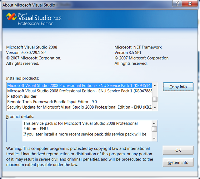
Service Pack 1 (SP1) may be installed at this point from the reference link provided [here]. Service packs as well as other installed products are viewed in Visual Studio 2008 via the About Microsoft Visual Studio. Installation of Service Pack 1 can be validated:
- In Visual Studio 2008 go to Help -> About Microsoft Visual Studio
- Under Installed products: find Microsoft Visual Studio 2008 Professional Edition – ENU Service Pack 1 (KB945140) KB945140
- Product details: for more information on the installation
2.1.1.3 Windows Embedded Compact 7 Platform Builder
To install the Platform Builder Snap-in for Visual Studio 2008, insert the DVD labeled Windows Embedded Compact 7 included with the Rapid Development Kit into the DVD ROM drive. The setup should start automatically. If not, open a Windows Explorer window, go to the DVD drive and startsetup.exe manually.
When completing the instructions, be sure to select Custom Install over Full Install to eliminate support for unneeded processor architectures, therefore, reducing the amount of disk space from 51.36GB to 10GB. Similarly, this will limit updates to only those necessary, directly correlating to shortened update time. In this case, the selection of the ARM v7 Architecture is required and can be modified at any point in the following way:
- Go to Program Features (Control Panel -> Programs -> Program Features)
- Highlight Windows Embedded Compact 7 from the list of installed programs
- Select Change
- In Customize Installation, select Modify
- Select/Deselect from Initial Options based on specific needs

Update Tool for Platform Builder
Windows Embedded Developer Updates (WEDU) is a helpful tool to receive notifications for new updates in Visual Studio. The process of manually checking for, installing, and configuring updates is simply replaced by an Add-in to the Tools menu, installed through the Compact 7 toolkit.
These updates can be setup and configured through Windows Embedded Compact 7. To apply registration, automatic configuration, and updates the Windows Embedded Compact 7 installer must be accessed:
- Go to Program Features (Control Panel -> Programs -> Program Features)
- Highlight Windows Embedded Compact 7 from the list of installed programs
- Select Change

By selecting Update, the installer provides a walk through for registration, update configuration, and execution of updates.

Registration is required to receive automatic notification, installation, and simple access to updates with WEDU. The registration process most likely was done during the initial installation of Windows Embedded Compact 7. However, if registration has yet to be completed, the installer provides the option to:
- Select Register
- Complete all required fields in the registration form
- Select Finish

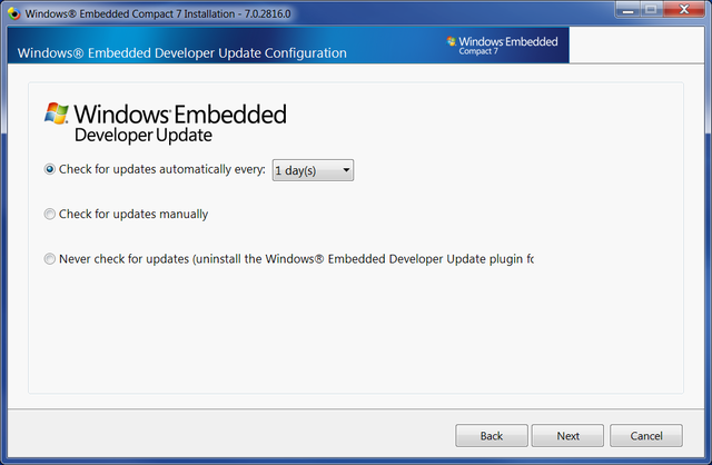
WEDU can be configured to automatically apply updates after registration. Select Configure Automatic Updates (Visual Studio® 2008 SP1 required) to not only turn on or off automatic updates, but install the Windows Embedded Developer Update Add-in for Visual Studio 2008 that can be accessed via the Tools menu.

From the options, WEDU can be tailored to specific requirements, in this example Check for updates automatically every: is selected with the drop down menu choice of 1 day(s).
The Windows Embedded Compact 7 Installer will check for modifications and updates, after reviewing the proposed alterations, select Install.

The installation source file is needed to perform current and subsequent updates, based on installation preferences insert the installation disk, browse to the location containing the update, or select Download to acquire the requested files from the Internet.

Acquisition and install make up the two part update process, upon successful update, Finish can be selected.

Updates can be automated or performed manually in Visual Studio 2008 (SP1 required) by the WEDU Add-in, Tools -> Windows Embedded Developer Update. Check for Updates and Configure Options are used for manually performing an update check and modification to existing update configuration options, respectfully.

2.1.2 File Installation
The phyCORE-OMAP44XX BSP can be installed by the executable file, the current version is labeled Phytec_OMAP4_Compact7.exe, on the PHYTEC FTP [here].
By installing the files to C:\WINCE700 directory directly, there is potential to overwrite binaries used by other BSPs. Therefore, it is recommended to install to an alternate directory such as C:\Phytec\OMAP44XX, back up existing files, and manually copy necessary files.
The following gives a general overview of each file system with corresponding directory location and description:
| Files | Location | Description |
|---|---|---|
| OMAP4Phytec | WINCE700\Platform | Sample BSP, adapts the OS to phyCORE-OMAP44XXhardware |
| OMAP4Phytec_Demo | WINCE700\OsDesigns | Sample OS Design for phyCORE-OMAP44XX |
| phyCORE-OMAP4430_SDK | phyCORE-OMAP44XX _CE7_SDK.msi | Sample SDK, set of libraries for developer to link without access to the OS design |
The files, either Source or Binary, can be unpacked in the following way:
- Move the top-level directory WINCE700\Platform\OMAP4Phytec and all its subdirectories and files to C:\WINCE700\Platform
- Move the top-level directory WINCE700\OsDesigns\OMAP4Phytec_Demo and all its subdirectories and files to C:\WINCE700\OsDesigns
- If Binary directories were unpacked and modules will be added that are built against the BSP, install the phyCORE-OMAP4430_CE7_SDK . Accept the default installation path of C:\Program Files (x86)\Windows CE Tools\SDKs\phyCORE_OMAP4430_SDK.

2.2 Board Setup
Power and host-PC connections to the target device as well as preparation of external media devices such as a SD Memory Card must be made. The hardware manual, included with the Rapid Development Kit, may be referred to for specific connection and location information.
2.2.1 Power
The primary input power for the phyCORE-OMAP44XX Carrier Board comes from the wall adapter jack, X6. Upon application of power, LEDs D14 - D17 should light up (green) and initial serial data will be sent by UART3 (top connector P1). The Carrier Board provides options for a warm reset or system power ON/OFF without the removal of the power source through push buttons S7 and S3, respectfully.
2.2.2 Serial
A serial connection is used as system communication for boot-up interaction throughout start-up and as a monitoring/debugging interface. This connection is made between the Host and UART3, top connector P1 on the phyCORE-OMAP44XX .
The following provides a summary of the serial settings required to allow console access over the serial port in a communications program on the host such as PuTTY:
| Setting | Value |
|---|---|
| Bits per second | 115200 bsp |
| Data bits | 8-bits |
| Stop-bit | 1 |
| Flow Control | None |
2.2.3 Ethernet
The Ethernet connection is used for flashing, downloading, and debugging images and applications. Connect the cross-over Ethernet cable to the Ethernet connector on the target (X9) and appropriate network card on the host. LINK (green) and SPEED LEDs (yellow) on the connector verify the connection.
2.2.4 SD Memory Card
A SD Memory Card that is properly formatted, holds the correct files, and inserted on the Carrier Board at SDMMC1 (X11) can be used to boot the BSP. This is accomplished by using the provided prepsd.bat tool:
- Insert the SD Card into the host machine
- Open a command prompt with administrator privileges
Right-click Start->All Programs->Accessories->Command Prompt and select Run As Administrator - Format the SD Card using 16k allocation units and set the partition to bootable for inserted SD Card (J: is the volume used in the following example).
prepsd.bat J: 16k
- Copy the files, from the correct directory to the SD Memory Card, Binary/SDCard_$LCDModel (where $LCDModel is LCD014, LCD017, LCD017_104S), in order:
MLOebootsd.rawboot.cfgNK.bin
- Properly eject the SD Card from host system
- Insert the SD Card into the SDMMC1 (X11) slot of the Carrier Board
Note: prepsd.bat is a personal script, if executed a user is at their own risk
2.3 Booting
The bootloader, one of the key software components included in the BSP, completes the required hardware initializations to download and run operating system images. The initial bootstrapper, bootloader, and NK make up the three software components needed to boot Windows Compact 7.
The RDK comes with binary images preinstalled. To update the images, the newly built as described in Section 3.3 or the default located on the PHYTEC America FTP [here] can be used. Refer to the Flashing Images section for information on how to flash these images.
2.3.1 Initiating and Restarting Boot
The boot process is initiated by powering on or resetting the device as described in Section 2.2.1. A power on or reset will start the ROM Bootloader (located in the OMAP44xx itself) and it will attempt to load the XLDR (MLO) from a prioritized list of locations. The default configuration of the RDK would have the order of NAND, then SDCard. For further configuration details see Section 2.3.3.
Booting may need to be restarted for access to the EBOOT configuration menu Section 2.3.3.1 to change current settings or to refresh broadcasted ‘BOOTME’ messages in the connection establishment between Platform Builder and the target device, Section 2.4.
2.3.2 Boot Mode
The boot mode, selected from the S5 dipswitch on the Carrier Board, determines the location of where the MLO is loaded from. The media-specific version of MLO will determine where EBOOT is loaded from.
2.3.2.1 NAND Boot
To boot from NAND, using the following switch settings:
S2-1 to S2-8 OFF

2.3.2.2 SD Card Boot
The SD Memory Card must be formatted and marked bootable as described in Section 2.3.1.4. To boot from SD Memory Card use the following switch settings:
S2-2, S2-3, and S2-5 ONS2-1, S2-4, S2-6 to S2-8 OFF

2.3.3 EBOOT
Loaded by MLO, EBOOT is used for downloading and launching the Operating System image (NK.bin. by default). EBOOT provides a default boot configuration as well as a method of setting that configuration and in some instances, modifying the media it supports.
2.3.3.1 Configuration Menu
By default, EBOOT gives five seconds to enter the configuration menu, in which the space key must be pressed. The wide variety of functions EBOOT provides in the configuration menu is given by the following:
- [1] Show Current Settings
- [2] Select Boot Device
- [3] Select Debug Device
- [4] Network Settings
- [5] eMMC Utilities
- [6] Set Device ID
- [7] Save Settings
- [0] Exit and Continue
2.3.3.2 Booting Options
The location of where NK.bin should be loaded and executed from is determined by EBOOT. If the configuration menu is not entered, the default environment will be used to continue the boot process. However, entering the EBOOT configuration menu allows the user to select the boot device and modify the default environment:
A variety of boot device selections is provided by EBOOT. For the Quickstart, two of the boot device selections are used, LAN911x Ethernet and NK from external SD slot. The boot device selection can be modified by:
- Start the bootloader
- Enter the configuration menu by pressing space at boot up
- Select EBOOT menu item [2] to enter the Select Boot Device menu
- Make boot device selection by entering the number corresponding to choice
Enter 1 for LAN911x Ethernet to download an image over Ethernet
Enter 6 for NK from external SD slot to download SD Card image - Select EBOOT menu item [7] to Save Settings
2.4 KITL Connection
The Kernel Independent Transport Layer (KITL) is an interface for device communication through debug message services, kernel debugger support, target control, release directory file system, and remote tools.
The KITL connection between the device and Platform Builder is made available over Ethernet. When the KITL output is enabled, to have a successful boot, there must be an association between the target device and Platform Builder. A one-time initial establishment between Platform Builder and the target device must be done. Thereafter, the connection will then be recognized for target attachment by selecting the proper device.
2.4.1 Create a KITL Connection
For a particular device, a KITL connection must be created once. This two part setup is done by adding a new device specific to the target in a Platform Builder target developed solution file and establishing a connection by responding to the bootloader network broadcasted ‘BOOTME’ messages, as outlined by the following:
Open Target Developed Solution File In Visual Studio, open a target developed solution file, such as the default NK.bin included in the Rapid Development Kit Binaries:
- In Visual Studio, go to File->Open Project/Solution
- Browse to the SDCard directory that matches the LCD Panel Binary/SDCard_$LCDModel
(where $LCDModel is LCD014, LCD017, LCD017_104S) - Under, Binary/SDCard_$LCDModel, select NK.bin
(where $LCDModel is LCD014, LCD017, LCD017_104S)
Add Device
A new device must be added for the phyCORE-OMAP44XX in Platform Builder through the Target Device Connectivity Options dialog box:
- In Platform Builder, go to Target->Connectivity Options
- Select Add Device
- Type OMAP4 for the New target device name
- Select Windows CE for the Associated OS Design/SDK
- Click Add

The Kernel Service Map property settings for the newly created OMAP4 device should be set to the following:
| Property | Selection |
|---|---|
| Kernel Download | Ethernet |
| Kernel Transport | Ethernet |
| Kernel Debugger | KdStub |
Communication Link Setup
A communication link is created upon acknowledgement in Platform Builder of a target device’s bootloader broadcast of ‘BOOTME’ messages over the network. Therefore, to establish a connection, Platform Builder must be in a listening state while EBOOT is in the proper configuration to broadcast.
The Ethernet Download Settings window is used to view Platform Builder and device connectivity state, this window is opened in the following way:
- With OMAP4 selected as the Target Device in the Target Device Connectivity Options dialog window
- Click Settings of Kernel Download: Ethernet to open the Ethernet Download Settings window

Keep the Ethernet Download Settings window open, acting in a listening state it will remain empty waiting for a ‘BOOTME’ message as a request from EBOOT on the target device.

Broadcast ‘BOOTME’ messages over the network from the target device:
- Boot the target device and enter the EBOOT configuration menu, as described in Section 2.3
- Using the serial console in the EBOOT Configuration Main Menu, enter [2] to Select Boot Device
- Enter [1] to select LAN911x Ethernet
- Enter [0] to Exit and Continue

As the serial console displays a series of ‘BOOTME’ messages, Platform Builder acknowledges the broadcast of the device by adding the device name to Active target devices in the Ethernet Download Settings window. The serial console displays the Device Name prior to issuing ‘BOOTME’ broadcast messages, the Device Name, SDP4430-61953 matches Target Device Name in Platform Builder.


By highlighting the device, additional information including the IP Address and Boot Loader Version will be displayed. By clicking Apply, the communication between Platform Builder and the target device will be finalized.

2.4.2 Verify Connection
With Platform Builder and the device being associated, any KITL connection to the board (Debug output, debugger, test transport, etc) will work. The connection to a device can be verified in the Target Device Connectivity Options window (Target -> Connectivity Options). With OMAP4 selected as the Device, the target boot name associated with the device will be present:

2.4.3 Attach Target
Having established and verified a KITL connection, Platform Builder can be connected to a target device. This connection between Platform Builder and the device must be made when images are to be downloaded or to successfully boot when the KITL output is enabled. In Platform Builder, withOMAP4 selected as the device, simply select Attach Device or go to Target->Attach Device.
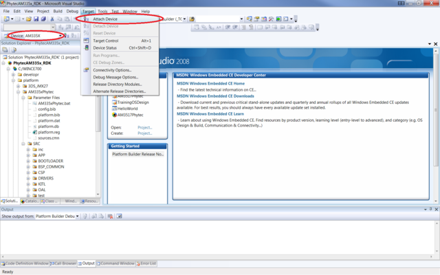
The Device Status window can be used to monitor the connection between Platform Builder and the target device. The window should open automatically following the attachment of the target, otherwise, in Platform Builder go to Target->Device Status.

3 Building a BSP
The sample OS Design included with the development kit allows demonstration of how to work with Platform Builder to build a custom BSP solution for the phyCORE-OMAP44XX. The OS images generated using Platform Builder as NK.bin files can be downloaded to a device as described inSection 2.3 by a KITL connection, setup in Section 2.4.
3.1 OS Design Setup
Open the sample OS Design, installed as OMAP4Phytec_Demo by the following steps:
- Open Visual Studio 2008
- From the menu bar select File->Open->Project/Solution
- Browse to: C:\WINCE700\OSDesigns\phyCORE-OMAP44XX
- Open the solution file, OMAP4Phytec_Demo.sln
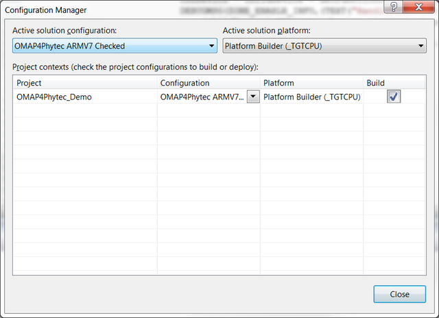
A build configuration of Release, Debug, or Checked must be selected. A Debug Build is rarely used because of the large resulting image it produces because of no optimizations. A fully optimized configuration is achieved through a Release Build configuration. With a Checked Build configuration, the optimizations of a Release Build are maintained but by enabling DEBUGMSG, DEBUGCHK, and ASSERT, debugging capabilities are made available. Therefore, a Checked Build would be a good choice for identification and diagnosis of OS issues.
To make a selection, in Visual Studio, open the Configuration Manager by going to Build->Configuration Manager and select a build configuration from the Active Solution configuration drop down menu:
3.2 Modifications to the OS Design
The OS Design can be modified with respect to the build configuration, platform settings, driver source, source code, parameter files, adding or deleting files to the workspace, and more.
Most commonly, modifications will be made by adding or deleting elements from the OS through the Catalog Items View window. The Catalog Items View window can be made viewable by going to View->Other Windows->Catalog Items View. The files of interest for modification are the Core OS and BSP; go to File->Save All to insure all Catalog item changes are saved.
| Files of Interest | Location | Content |
|---|---|---|
| Core OS | OMAP4Phytec_Demo ->Core OS->Windows Embedded Compact | Features of the OS Example: Applications such as ActiveSync and WordPad |
| BSP | OMAP4Phytec_Demo->Third Party->BSP->OMAP4Phytec_Demo | Device drivers provided in the PHYTEC BSP Kit |

3.3 Building the OS Design
The OS Image can be built by performing a Sysgen on the solution; done by Build->Build Solution.
A Sysgen can also be executed via the command prompt, opened from Build->Open Release Directory in Build Window:
blddemo –q
A full build is expected to take 20-30 minutes, this estimate will vary depending on the OS features and Host performance. For future modifications to the same sample OS Design, a full Sysgen is not required and taking advantage of optimized build options specific to modifications will shorten the build time.
The files generated can be found in C:\WINCE700\OsDesigns\OMAP4Phytec_Demo\OMAP4Phytec_Demo\RelDir under the build configuration selected.
3.4 Creating a new SDK for an OS Design
A new SDK is necessary when modifications are made to the sample OS Design to allow headers and libraries for the OS configuration to be up-to-date for application development.
The SDK can be created as a MSI file after a fresh build by the following:
- Select Project->Add New SDK with current OS configuration opened in Visual Studio’s Solution Explorer
- Complete relevant sections to label and name resulting SDK MSI installer file
- Find the newly created SDK in Visual Studio’s Solution Explorer
- Right Click and select Build


After exiting the project and uninstalling any previous SDK’s, the new SDK can be installed by running the MSI file, the installation should be similar to that of 2.1.2.
4 Flashing Images
The three software components, MLO, EBOOT, and NK needed to boot Windows Compact 7, if modified will have to be updated in NAND Flash.
4.1 Building Images to be Flashed
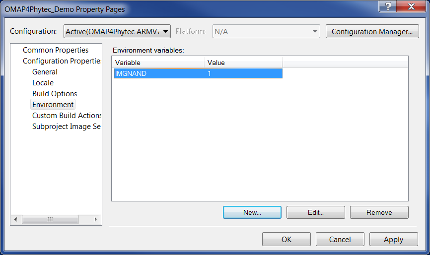
The build environment must be modified to allow flashing. Flashing files to NAND, in Visual Studio/Platform Builder, assuming the OS has already been built, is done by setting the environment variable IMGNAND=1 and making a Run-Time image. To build under this configuration:
- In Visual Studio/Platform Builder, go to Project->Properties->Configuration Properties->Environment
- Set the IMGNAND environment variable equal to 1 (IMGNAND = 1)
- Select Build->Make Run-Time Image
This can also be done via the command prompt, opened from Build->Open Release Directory in Build Window, and executing:
set IMGNAND = 1
makeimg
The images created are located in the Release Directory, as mentioned in Section 3.3 and include:
| File | Name |
|---|---|
| x-loader | xldrnand.bin |
| bootloader | ebootnd.bin |
| OS | NK.bin |
4.2 Flashing NK.bin
NK.bin can be burned to NAND Flash with Platform Builder or SD Memory Card using file built in Section 4.1. By downloading NK.bin to the device with either Platform Builder or SD Memory Card, as described in Section 2.3.4.2, the bootloader will automatically program NK.bin into NAND flash.
4.3 Flashing Bootloaders
The initial bootstrap loader and bootloader can also be flashed to NAND by a combination of SD Card booting and Platform Builder image downloading:
- Boot the OS from SD Card as described in Sections 2.3.3.2 and 2.3.4.2
- In Platform Builder, go to Project->Properties->Configuration Properties->General
- Select either xldrnd.bin or ebootnd.bin, built in Section 4.1, from the Target file name for debugger drop down menu.
- Boot the system, connect to the device, and download the image
