...
- Connect the LVDS display cable between the display and connector X9 on the phyBOARD-Mira.
- Connect the LCD backlight and power cable between the display and connector X8.
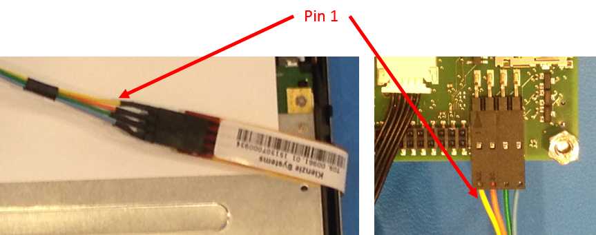
Connect the 4-wire touch cable between the display and X21.


Info title Note When connecting the 4-wire touch cable please note the location of the yellow wire to determine the location of pin 1.
- Turn the phyBOARD-Mira and display so it is face up. It should look like the following.

The BSP has already been configured to support the display but it must be enabled as an expansion in Barebox. To activate the display enter the following in Barebox. See the phyBOARD-Mira i.MX6 Quickstart for more information.
Code Block edit /env/config-expansions
Add the following line.
Code Block . /env/expansions/imx6qdl-mira-enable-lvds # Enable for 10" LVDS Display AUO G104SN02-V2 with resistive touch
- Save and exit using CTRL+D
- Restart the board
On the first boot a touch screen calibration is recommended. To run this the default Qt application must be stopped. After calibration it can be restarted.
Code Block systemctl stop qt5demo.service ts_calibrate systemctl start qt5demo.service
For additional information on using display, touch, and backlight control refer to the phyBOARD-Mira i.MX6 Application Guide.
Related articles
| Content by Label | ||||||||||||||||||
|---|---|---|---|---|---|---|---|---|---|---|---|---|---|---|---|---|---|---|
|
...