Phytec中国的wiki
support@phytec.cn![]()
热线:0755-61802110-803
Page History
| Table of Contents |
|---|
GPIO
Kernel有一部分已经写好的gpio功能,如下面这个文档所写:
https://git.phytec.de/linux-mainline/tree/Documentation/gpio/drivers-on-gpio.txt?h=v4.9.98-phy
本文也写了一些接口的用法如gpio的LED,以及按键。
| Code Block | ||
|---|---|---|
| ||
- leds-gpio: drivers/leds/leds-gpio.c will handle LEDs connected to GPIO lines, giving you the LED sysfs interface - ledtrig-gpio: drivers/leds/trigger/ledtrig-gpio.c will provide a LED trigger, i.e. a LED will turn on/off in response to a GPIO line going high or low (and that LED may in turn use the leds-gpio as per above). - gpio-keys: drivers/input/keyboard/gpio_keys.c is used when your GPIO line can generate interrupts in response to a key press. Also supports debounce. - gpio-keys-polled: drivers/input/keyboard/gpio_keys_polled.c is used when your GPIO line cannot generate interrupts, so it needs to be periodically polled by a timer. - gpio_mouse: drivers/input/mouse/gpio_mouse.c is used to provide a mouse with up to three buttons by simply using GPIOs and no mouse port. You can cut the mouse cable and connect the wires to GPIO lines or solder a mouse connector to the lines for a more permanent solution of this type. - gpio-beeper: drivers/input/misc/gpio-beeper.c is used to provide a beep from an external speaker connected to a GPIO line. - gpio-tilt-polled: drivers/input/misc/gpio_tilt_polled.c provides tilt detection switches using GPIO, which is useful for your homebrewn pinball machine if for nothing else. It can detect different tilt angles of the monitored object. - extcon-gpio: drivers/extcon/extcon-gpio.c is used when you need to read an external connector status, such as a headset line for an audio driver or an HDMI connector. It will provide a better userspace sysfs interface than GPIO. - restart-gpio: drivers/power/reset/gpio-restart.c is used to restart/reboot the system by pulling a GPIO line and will register a restart handler so userspace can issue the right system call to restart the system. - poweroff-gpio: drivers/power/reset/gpio-poweroff.c is used to power the system down by pulling a GPIO line and will register a pm_power_off() callback so that userspace can issue the right system call to power down the system. - gpio-gate-clock: drivers/clk/clk-gpio.c is used to control a gated clock (off/on) that uses a GPIO, and integrated with the clock subsystem. - i2c-gpio: drivers/i2c/busses/i2c-gpio.c is used to drive an I2C bus (two wires, SDA and SCL lines) by hammering (bitbang) two GPIO lines. It will appear as any other I2C bus to the system and makes it possible to connect drivers for the I2C devices on the bus like any other I2C bus driver. - spi_gpio: drivers/spi/spi-gpio.c is used to drive an SPI bus (variable number of wires, at least SCK and optionally MISO, MOSI and chip select lines) using GPIO hammering (bitbang). It will appear as any other SPI bus on the system and makes it possible to connect drivers for SPI devices on the bus like any other SPI bus driver. For example any MMC/SD card can then be connected to this SPI by using the mmc_spi host from the MMC/SD card subsystem. - w1-gpio: drivers/w1/masters/w1-gpio.c is used to drive a one-wire bus using a GPIO line, integrating with the W1 subsystem and handling devices on the bus like any other W1 device. - gpio-fan: drivers/hwmon/gpio-fan.c is used to control a fan for cooling the system, connected to a GPIO line (and optionally a GPIO alarm line), presenting all the right in-kernel and sysfs interfaces to make your system not overheat. - gpio-regulator: drivers/regulator/gpio-regulator.c is used to control a regulator providing a certain voltage by pulling a GPIO line, integrating with the regulator subsystem and giving you all the right interfaces. - gpio-wdt: drivers/watchdog/gpio_wdt.c is used to provide a watchdog timer that will periodically "ping" a hardware connected to a GPIO line by toggling it from 1-to-0-to-1. If that hardware does not receive its "ping" periodically, it will reset the system. - gpio-nand: drivers/mtd/nand/gpio.c is used to connect a NAND flash chip to a set of simple GPIO lines: RDY, NCE, ALE, CLE, NWP. It interacts with the NAND flash MTD subsystem and provides chip access and partition parsing like any other NAND driving hardware. |
因此如果所用的功能在kernel中有实现,则可以直接使用内核提供的接口,如LED/按键,而如果并未找到,则可以使用下面表格描述的应用层接口来访问GPIO。
首先要确定该IO口的pinmux是否是GPIO,大多数的io口上电后默认是GPIO,这个可以在处理器的datasheet中查找。
但有时IO口的配置会被后边的bootloader修改为其他配置,因此最保险的方法是将要使用的GPIO都在设备树中将MUX/复用功能定义出来:
| 参考来源 | 配置 | |||||||
|---|---|---|---|---|---|---|---|---|
| am335x-pcm-953.dtsi |
| |||||||
| imx6qdl-phytec-pfla02.dtsi |
|
其他设备树的配置请参考:
linux内核设备树修改指南 / linux kernel device tree modify guide
中的pinmux部分。
接下来是不同对应不同版本内核的GPIO使用方法。
| gpio字符设备方法 | gpiosys方法 | ||||||||||||||||||||||
|---|---|---|---|---|---|---|---|---|---|---|---|---|---|---|---|---|---|---|---|---|---|---|---|
适用的内核版本 使用uname -r查询 | V4.8或之后的版本 | V4.8之前的版本 | |||||||||||||||||||||
| 命令行操作方法 | 设置gpio4的22引脚为低:
读取gpio4的22引脚,同时会设置引脚为输入:
更多例子: |
| |||||||||||||||||||||
| 程序开发 | https://git.kernel.org/pub/scm/libs/libgpiod/libgpiod.git 可以直接参考其中tools中各个工具如: https://git.kernel.org/pub/scm/libs/libgpiod/libgpiod.git/tree/tools/gpioset.c 的代码 |
KEY
设备树gpio_keys配置文档:
https://www.kernel.org/doc/Documentation/devicetree/bindings/input/gpio-keys.txt
| Code Block | ||||||
|---|---|---|---|---|---|---|
| ||||||
&iomuxc {
	pinctrl_gpio_keys: gpiokeysgrp {
		fsl,pins = <
			MX6QDL_PAD_SD3_DAT6__GPIO6_IO18		0x1b0b0
			MX6QDL_PAD_CSI0_DAT10__GPIO5_IO28	0x1b0b0
		>;
	};
};

/ {
	gpio-keys {
		compatible = "gpio-keys";
		pinctrl-names = "default";
		pinctrl-0 = <&pinctrl_gpio_keys>;
		status = "disabled";

		home {
			label = "Home";
			gpios = <&gpio6 18 GPIO_ACTIVE_LOW>;
			linux,code = <KEY_HOME>;
		};

		power {
			label = "Power Button";
			gpios = <&gpio5 28 GPIO_ACTIVE_LOW>;
			linux,code = <KEY_POWER>;
			gpio-key,wakeup;
		};
	};
}; |
测试按键事件:
| Code Block | ||||
|---|---|---|---|---|
| ||||
$ evtest No device specified, trying to scan all of /dev/input/event* Available devices: /dev/input/event0: stmpe-ts /dev/input/event1: gpio-keys Select the device event number [0-1]:1 |
LED
gpio-leds设备树配置文档说明:
https://www.kernel.org/doc/Documentation/devicetree/bindings/leds/leds-gpio.txt
| Code Block | ||||||
|---|---|---|---|---|---|---|
| ||||||
&iomuxc {
	pinctrl_user_leds: userledsgrp {
		fsl,pins = <
			MX6QDL_PAD_SD3_DAT4__GPIO7_IO01		0x1b0b0
			MX6QDL_PAD_SD3_DAT5__GPIO7_IO00		0x1b0b0
			MX6QDL_PAD_CSI0_DAT11__GPIO5_IO29	0x1b0b0
		>;
	};
};

/ {
	user_leds: user-leds {
		compatible = "gpio-leds";
		pinctrl-names = "default";
		pinctrl-0 = <&pinctrl_user_leds>;
		status = "disabled";

		user-led1 {
			gpios = <&gpio7 1 GPIO_ACTIVE_HIGH>;
			linux,default-trigger = "gpio";
			default-state = "on";
		};

		user-led2 {
			gpios = <&gpio7 0 GPIO_ACTIVE_HIGH>;
			linux,default-trigger = "gpio";
			default-state = "on";
		};

		user-led3 {
			gpios = <&gpio5 29 GPIO_ACTIVE_HIGH>;
			linux,default-trigger = "gpio";
			default-state = "on";
		};
	};
}; |
linux上操作led:
查找所有可用的led:
| Code Block | ||||
|---|---|---|---|---|
| ||||
$ ls /sys/class/leds mira-blue mira-red mmc1:: user-led1 user-led3 mira-green mmc0:: phycore-green user-led2 |
打开led:
| Code Block | ||||
|---|---|---|---|---|
| ||||
$ echo 255 > /sys/class/leds/user-led1/brightness |
| Note |
|---|
如果该led硬件上不支持亮度选择的话, 输出任何一个非零数值都能点亮该led. |
关闭led:
| Code Block | ||||
|---|---|---|---|---|
| ||||
$ echo 0 > /sys/class/leds/user-led1/brightness |
闪烁led:
| Code Block | ||||
|---|---|---|---|---|
| ||||
$ echo timer > /sys/class/leds/user-led1/trigger $ echo 200 > /sys/class/leds/user-led1/delay_on #设置打开led时间 $ echo 200 > /sys/class/leds/user-led1/delay_off #设置关闭led时间 |
串口
| SOC | 串口设备名称 | 备注 |
|---|---|---|
| am335x | /dev/ttyO2 | 注意是字母O,数字为串口号 |
| imx6/6ul/7 | /dev/ttymxc2 | 数字为串口号 |

首先需要设置串口参数
| Code Block | ||||||
|---|---|---|---|---|---|---|
| ||||||
stty -F /dev/ttyO2 115200 raw |
如果是特殊波特率,需要使用如的方法来配置
可以使用 echo 来发送数据到串口
| Code Block | ||||||
|---|---|---|---|---|---|---|
| ||||||
echo "hello~tty device" > /dev/ttyO2 |
然后就可以在接口处看到输出结果。
使用 cat 来接收数据
| Code Block | ||||||
|---|---|---|---|---|---|---|
| ||||||
cat /dev/ttyO2 |
注意此时会有echo返回,如果想关闭echo功能可以通过stty设置
| Code Block | ||||||
|---|---|---|---|---|---|---|
| ||||||
stty -F /dev/ttyO2 115200 -onlcr -iexten -echo -echoe -echok -echoctl -echoke raw |
CAN
我们的开发板上的CAN口一般为一个DB9接口,它的引脚定义如下:
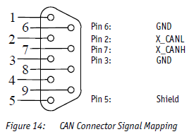

请按照座子中的编号来连接,2&7引脚为信号,3&6脚为地。
而这个也是CAN最通用的引脚顺序 https://en.wikipedia.org/wiki/CAN_bus#Layers
高速CAN(ISO 11898-2 High Speed CAN)接口需要将接线的两端用120Ω的电阻端接
图来自 http://www.ni.com/white-paper/9759/en/
我们的开发板一般都配一个跳线帽来使能这个120Ω的电阻(如下图中的JP9)。

在连接两个设备时,共地不是必须的,只需要对应连接CAN_L,CAN_H即可。
长距离高噪声的环境下对线缆和屏蔽地等接法和选型有要求,请阅读相关材料。
CAN的软件配置位于
/lib/systemd/system/can0.service
默认是500k的速率。
可以使用
| Code Block | ||||
|---|---|---|---|---|
| ||||
cansend can0 123#45.67 |
测试发送,使用
| Code Block | ||||
|---|---|---|---|---|
| ||||
candump can0 |
测试接收,另外如果不能收发请注意是否处在bus-off状态,使用下面的指令来检查。
| Code Block | ||||
|---|---|---|---|---|
| ||||
ip -d -s link show can0


2: can0: <NOARP,UP,LOWER_UP,ECHO> mtu 16 qdisc pfifo_fast state UNKNOWN mode DEFAULT group default qlen 10
    link/can  promiscuity 0
    can state ERROR-ACTIVE (berr-counter tx 0 rx 0) restart-ms 0
          bitrate 500000 sample-point 0.800
          tq 400 prop-seg 1 phase-seg1 2 phase-seg2 1 sjw 1
          c_can: tseg1 2..16 tseg2 1..8 sjw 1..4 brp 1..1024 brp-inc 1
          clock 25000000
          re-started bus-errors arbit-lost error-warn error-pass bus-off
          0          0          0          0          0          0         numtxqueues 1 gso_max_size 65536 gso_max_segs 65535
    RX: bytes  packets  errors  dropped overrun mcast
    0          0        0       0       0       0
    TX: bytes  packets  errors  dropped carrier collsns
0 0 0 0 0 0 |
EEPROM
开发板进入根目录/下查找eeprom的位置
| Code Block | ||||
|---|---|---|---|---|
| ||||
root@phycore-am335x-1:~# cd / root@phycore-am335x-1:/# find . -name eeprom ./sys/devices/platform/ocp/44e0b000.i2c/i2c-0/0-0052/eeprom |
读eeprom的前1024个字节并在屏幕上输出
| Code Block | ||||
|---|---|---|---|---|
| ||||
root@phycore-am335x-1:/# dd if=/sys/devices/platform/ocp/44e0b000.i2c/i2c-0/0-0052/eeprom bs=1 count=1024 | od -x 0000000 55aa 6850 7479 6365 4d2d 7365 7473 6365 0000020 6e68 6b69 ffff ffff ffff ffff ffff ffff 0000040 ffff ffff ffff ffff ffff ffff ffff ffff * 0002000 1024+0 records in 1024+0 records out |
对eeprom的全部字节写入0操作
| Code Block | ||||
|---|---|---|---|---|
| ||||
root@phycore-am335x-1:/# dd if=/dev/zero of=/sys/devices/platform/ocp/44e0b000.i2c/i2c-0/0-0052/eeprom bs=4096 count=1 1+0 records in 1+0 records out root@phycore-am335x-1:/# dd if=/sys/devices/platform/ocp/44e0b000.i2c/i2c-0/0-0052/eeprom bs=1 count=1024 | od -x 0000000 0000 0000 0000 0000 0000 0000 0000 0000 * 0002000 1024+0 records in 1024+0 records out |
测试磁盘(SD/NAND/SATA)的速度
测试读取速度
| Code Block | ||||
|---|---|---|---|---|
| ||||
hdparm -Tt /dev/sda |
测试写入速度
| Code Block | ||||
|---|---|---|---|---|
| ||||
dd if=/dev/zero of=/tmp/output bs=8k count=10k |
| Code Block | ||||
|---|---|---|---|---|
| ||||
iozone -a -g 256M -s 256M -b file.xls |
怎样设置RTC
| Code Block | ||||
|---|---|---|---|---|
| ||||
date -s "2017-7-17 15:44" |
设置时间为07月17日,15点44分,2017
| Code Block | ||||
|---|---|---|---|---|
| ||||
hwclock -w -u |
更新RTC时间。
另,如果RTC未设置过时间,则会打印内核信息
| Code Block | ||||
|---|---|---|---|---|
| ||||
[ 1.943438] rtc-m41t80 0-0068: Oscillator failure, data is invalid. [ 1.950394] rtc-m41t80 0-0068: rtc core: registered rv4162 as rtc0 |
怎样使用RTC1/RTC2来作为系统时钟
部分核心板具有多个RTC,如phyCORE i.MX6核心板板载2个RTC,一个是i.MX6 CPU自己带的SNVS rtc,另一个是PMIC的RTC,由于这两个RTC性能不是很好,因此我们开发板又加了一个RTC,接在I2C总线上。
在系统中,你可以用
| Code Block | ||||
|---|---|---|---|---|
| ||||
oot@phyboard-mira-imx6-3:/sys/class/rtc# cat rtc*/name rtc-m41t80 0-0068 da9063-rtc da9062-rtc snvs_rtc 20cc000.snvs:snvs-rtc-lp |
这样的方法来检查/dev/rtc#和硬件RTC的对应关系,而这个是在设备树中由 aliases 节点配置,如:
| Code Block | ||||
|---|---|---|---|---|
| ||||
 aliases {
 	rtc1 = &da9062_rtc;
	rtc2 = &snvs_rtc;
}; |
接下来,你可以用之前的指令来设定某个RTC的时间,或者读取RTC的时间并写入系统:
| Code Block | ||||
|---|---|---|---|---|
| ||||
读取入系统: hwclock -s -u -f /dev/rtc# 写入RTC: hwclock -w -u -f /dev/rtc# |
如果要设定系统开机默认使用的RTC,需要配置内核的menuconfig(https://cateee.net/lkddb/web-lkddb/RTC_HCTOSYS_DEVICE.html),然后重新编译来实现:

I2C接口
在测试i2c接口时,主要通过i2ctools这个工具,文档:https://manpages.debian.org/unstable/i2c-tools/index.html 。
如:
| Code Block | ||||
|---|---|---|---|---|
| ||||
imx7d-phyboard-zeta-001:~# i2cdetect 1
WARNING! This program can confuse your I2C bus, cause data loss and worse!
I will probe file /dev/i2c-1.
I will probe address range 0x03-0x77.
Continue? [Y/n] y
     0  1  2  3  4  5  6  7  8  9  a  b  c  d  e  f
00:          -- -- -- -- -- -- -- -- -- -- -- -- --
10: -- -- -- -- -- -- -- -- -- -- -- -- -- -- -- --
20: -- -- -- -- -- -- -- -- -- -- -- -- -- -- -- --
30: -- -- -- -- -- -- -- -- -- -- -- -- -- -- -- --
40: -- UU -- -- -- -- -- -- -- -- -- -- -- -- -- --
50: -- UU -- -- -- -- -- -- -- -- -- -- -- -- -- --
60: -- -- -- -- -- -- -- -- -- -- -- -- -- -- -- --
70: -- -- -- -- -- -- -- -- |
以上例子使用i2cdetect工具检测i2c1总线上,每个地址对i2c指令是否有反应。
通过i2ctools工具还可以实现读取某个i2c设备的寄存器,设置寄存器等功能。
需要注意的是,如果有驱动在使用这个地址(上面例子中的UU),则不能通过i2ctools访问,需要访问的话需要在设备树中注释掉驱动。
| Code Block | ||||
|---|---|---|---|---|
| ||||
imx7d-phyboard-zeta-001:~# i2cdump 1 0x41 No size specified (using byte-data access) Error: Could not set address to 0x41: Device or resource busy |
要开发操作i2c接口的应用程序,可以参考一下i2ctools的源码。
https://github.com/mozilla-b2g/i2c-tools
SPI
请参考内核提供的例子:
https://git.phytec.de/linux-mainline/tree/tools/spi?h=v4.9.98-phy
以及我们的文档:spidev测试方法 /how to test spidev
CPU的使用
CPU频率设置
在linux下有专门的驱动cpufreq来控制/设定cpu的工作频率,很多CPU都可以根据工作负载来动态的调整工作频率。
该驱动的文档为 https://www.kernel.org/doc/Documentation/cpu-freq/user-guide.txt
| 事项 | 代码 | |||||||
|---|---|---|---|---|---|---|---|---|
| 查看当前工作频率 |
| |||||||
| 查看可设置的频率列表 |
| |||||||
| 设置最大的调整频率 |
| |||||||
查看可用的频率调节器(governors) https://www.kernel.org/doc/Documentation/cpu-freq/governors.txt |
| |||||||
| 设置为固定的频率 |
|
关闭CPU/关闭核心
查看CPU核数量:
| Code Block | ||||
|---|---|---|---|---|
| ||||
ls /sys/devices/system/cpu -1 |
然后可通过以下指令关闭
| Code Block | ||||
|---|---|---|---|---|
| ||||
echo 0 > /sys/devices/system/cpu/cpu3/online |
关闭后echo 1 可以打开。
Overview
Content Tools
Activity
Tasks