Non-Kit SOM
If working with a non-kit SOM, there are additional steps required to build this release for your configuration. Please view the notes in the Building the BSP from Source and Built Images sections for the applicable differences. For each SOM configuration there may be a required change to the Linux dts, the yocto MACHINE value, and the output images.
This Quickstart provides you with the tools and know-how to install and work with the Linux Board Support Package (BSP) for the phyCORE-AM572x Rapid Development Kit. This Quickstart shows you how to do everything from installing the appropriate tools and source, to building custom kernels, to deploying the OS, to exercising the software and hardware. Please refer to the phyCORE-AM572x Hardware Manual for specific information on board-level features such as jumper configuration, memory mapping and pin layout for the phyCORE-AM572x System on Module (SOM) and baseboard. Additionally, gain access to the SOM and baseboard schematics for the phyCORE-AM572x Rapid Development Kit by registering at the following: http://phytec.com/support/registration/.
Requirements
The following system requirements are necessary to successfully complete this Quickstart. Deviations from these requirements may suffice, or may have other workarounds.
Software
A modern GNU/Linux Operating host system either natively or via a virtual machine:
Ubuntu 16.04 LTS recommended, 64-bit required. Other distributions will likely work, please note that some setup information as well as OS-specific commands and paths may differ.
If using a virtual machine, VMWare Workstation, VMWare Player, and VirtualBox are all viable solutions.
Root access to your Linux Host PC. Some commands in the Quickstart will not work if you don’t have sudo access (ex. package installation, formatting SD card).
At least 210GB free on target build partition and at least 4GB of RAM available to the build host.
SD card reader operational under Linux.
If you do not have SD card access under Linux then formatting, copying the bootloader, and mounting the root file system on an SD card will not be possible.
Active Internet connection
Hardware
- phyCORE-AM572x System on Module (PCM-057)
- phyCORE-AM572x Baseboard (PCM-948)
- Serial cable (RS-232)
- Ethernet cable
- SD Card (8GB or more recommended for flashing and development)
AC adapter supplying 12VDC / min. 2A
See release notes for supported SOM and carrier board versions.
Connector Interfaces
Use the following as a reference for the connector interfaces on the phyCORE-AM572x Rapid Development Kit that will be used in this Quickstart.

Getting Started With Binary Images
This section is designed to get the board up-and-running with pre-built images.
Booting the Pre-built Images
The section was designed to show you how to boot the phyCORE-AM572x Rapid Development Kit with the pre-built demo images.
- Connect the kit supplied serial cable from a free serial port on your host PC to the DB9 connector X18 on the carrier board. This is the UART3 communication channel with the AM572x at RS-232 levels.
- Connect the kit supplied Ethernet cable from the Ethernet connector X7 on the carrier board to your network hub, router, or switch. If you do not have an Ethernet connection you can postpone this step, Linux will boot without the need for Ethernet connectivity but having the connection will significantly reduce your boot time.
- Start your favorite terminal software (such as Minicom or TeraTerm) on your host PC and configure it for 115200 baud, 8 data bits, no parity, and 1 stop bit (8n1) with no handshake.
- Plug the kit supplied 12 V power adapter into the power connector X4 on the carrier board. You will instantly see power LEDs VCC_5V0 and VCC_3V3 on the carrier board light up solid green.
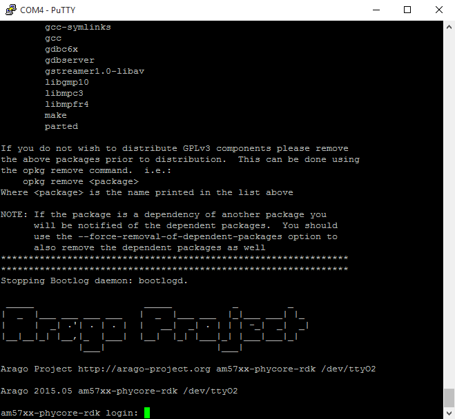
Press the power button S2 on the carrier board. You will now see power LEDs VDD_3V3, VDD_5V0, and VDD_12V0 on the carrier board light up a solid green. You will also start to see console output on your terminal window. If everything was done correctly the board should boot completely into Linux, arriving at a am572x-phycore-rdk prompt. The default login account is root with an empty password. Note that the first time the board is booted it will takes a little while for the SSH server to generate new keys. Subsequent boots should be faster.
Troubleshooting
Not seeing any output on the console?
- Check that you have setup the terminal software correctly per step 5.
- Make sure to press the power button S2 on the carrier board. Unlike some other PHYTEC boards, the phyCORE-AM572x RDK does not get powered on simply by plugging in the power supply.
- Create a Bootable SD Card with the release images from the PHYTEC ARTIFACTORY, then configure the board to boot from SD/MMC (Selecting Boot Modes). After booting, you can restore your eMMC contents by following the Flashing Images to eMMC section.
Booting Images from Source
Development Host Setup
Host Debian Packages
Yocto development requires certain packages to be installed. Run the following commands to ensure you have the packages installed:
sudo apt-get install git build-essential python diffstat texinfo gawk chrpath dos2unix wget unzip socat doxygen libc6:i386 libncurses5:i386 libstdc++6:i386 libz1:i386 lib32stdc++6 lib32ncurses5 lib32z1 libc6-dev-i386 cpio gcc-multilib
The above is the recommended package installation for development on a Ubuntu 16.04 LTS Linux distribution. For a breakdown of the packages as well as a list of packages required for other Linux distributions, see the "Required Packages for the Host Development System" section in the Yocto Project Reference Manual: http://www.yoctoproject.org/docs/2.2/ref-manual/ref-manual.html#required-packages-for-the-host-development-system
Verify that the preferred shell for your Host PC is ''bash'' and not ''dash'':
sudo dpkg-reconfigure dash
# Respond "No" to the prompt asking "Install dash as /bin/sh?"
bash
Repo Tool
Download and install the repo tool. This tool is used to obtain Yocto source from Git.
cd /opt
sudo mkdir bin
# /opt/ directory has root permission, change the permissions so your user account can access this folder. In the following replace <user> with your specific username
sudo chown -R <user>: bin

cd bin
curl http://commondatastorage.googleapis.com/git-repo-downloads/repo > ./repo
# add directory that contains repo to your path
chmod a+x repo
Add the repo directory in your PATH, using export from the command line or permanently by including it in .bashrc:
export PATH=/opt/bin/:$PATH
Git Setup
If you have not yet configured your Git environment on this machine, please execute the following commands to set your user name and email address. See here for more information on getting started with Git.
git config --global user.email "your@email.com"
git config --global user.name "Your Name"
git config --global http.sslcainfo /etc/ssl/certs/ca-certificates.crt
Server Setup (Optional)
Building the BSP from Source
Create a directory which will house your BSP development. In this example the BSP directory is /opt/PHYTEC_BSPs/. This is not a requirement and if another location is preferred (ex. ~/PHYTEC_BSPs) feel free to modify. We recommend using /opt over your HOME directory to avoid errors attributed to ~ syntax as well as the sudo requirement for the root filesystem and automation package building. We also recommend creating a package download directory (yocto_dl) separate from the yocto tree (yocto_ti), as it makes resetting the build environment easier and subsequent build times much faster.
Setup the BSP Directory:
sudo mkdir /opt/PHYTEC_BSPs
cd /opt/


# /opt/ directory has root permission, change the permissions so your user account can access this folder. In the following replace <user> with your specific username
sudo chown -R <user>: PHYTEC_BSPs


cd PHYTEC_BSPs
mkdir yocto_ti
mkdir yocto_dl
cd yocto_ti
export YOCTO_DIR=`pwd`
At this point you will now be able to navigate to the Yocto directory using the $YOCTO_DIR environment variable.
Install the Linaro Toolchain:
Run the following commands to install the Linaro Toolchain:
wget http://releases.linaro.org/components/toolchain/binaries/6.2-2016.11/arm-linux-gnueabihf/gcc-linaro-6.2.1-2016.11-x86_64_arm-linux-gnueabihf.tar.xz
tar -Jxvf gcc-linaro-6.2.1-2016.11-x86_64_arm-linux-gnueabihf.tar.xz -C /opt/PHYTEC_BSPs
rm gcc-linaro-6.2.1-2016.11-x86_64_arm-linux-gnueabihf.tar.xz
Download the BSP Meta Layers
Download the manifest file for the AM57xx PD18.1.0 BSP:
cd $YOCTO_DIR
repo init -u https://stash.phytec.com/scm/pub/manifests-phytec.git -b am57xx -m PD18.1.0.xml
Download the Yocto meta layers specified in the manifest file:
repo sync
Start the Build
If working with a non-kit SOM, please expand the content below for additional instructions.
Run the Yocto build directory setup script. The TEMPLATECONF variable is used to set the source of the local configuration files (conf/bblayers.conf and conf/local.conf), which are located in the meta-phytec layer:
cd $YOCTO_DIR
TEMPLATECONF=$YOCTO_DIR/sources/meta-phytec/meta-phytec-ti/conf MACHINE=am572x-phycore-rdk source sources/oe-core/oe-init-build-env build
Open the build/conf/local.conf file using your favorite editor and modify the the download directory to:
DL_DIR ?= "/opt/PHYTEC_BSPs/yocto_dl"
Maximize build efficiency by modifying the BB_NUMBER_THREADS variable to suit your host development system. This sets the maximum number of tasks that BitBake should run in parallel. Also set the variable PARALLEL_MAKE to specify the number of threads that make can run. By default, these are set to 4 in build/conf/local.conf:
# Parallelism options - based on cpu count
BB_NUMBER_THREADS ?= "4"
PARALLEL_MAKE ?= "-j 4"
Be sure to save your changes to the local.conf file before closing.
The setup is complete and you now have everything to complete a build. This BSP has been tested with the arago-core-tisdk-image, it is suggested that you start with this image before building other images. Alternate images are located in various meta layers at yocto_ti/sources/meta*/recipes*/images/*.bb. They can be found using the command bitbake-layers show-recipes "*-image*" in $YOCTO_DIR/build/.
The default build target is arago-core-tisdk-image, which includes all TISDK demos and support.
In the interest of creating a smaller image that still supports all libraries and graphics features, but without many of the demos, we recommend using phytec-tisdk-image.
If building for am5726-phycore-rdk, the video and graphics support will be removed from the output regardless of the image target as am5726 does not support these features.
The following will start a build from scratch including installation of the toolchain as well as bootloader, Linux kernel, and root filesystem images.
cd $YOCTO_DIR/build
export PATH=/opt/PHYTEC_BSPs/gcc-linaro-6.2.1-2016.11-x86_64_arm-linux-gnueabihf/bin:$PATH
MACHINE=am572x-phycore-rdk bitbake arago-core-tisdk-image
Built Images
If working with a non-kit SOM, please expand the content below for additional instructions.
All images generated by bitbake are deployed to $YOCTO_DIR/build/arago-tmp-external-linaro-toolchain/deploy/images/<machine>:
- Bootloader: MLO, u-boot.img
- Kernel: zImage
- Kernel device tree file: zImage-am572x-phycore-rdk.dtb
- Root Filesystem: tisdk-rootfs-image-am572x-phycore-rdk.tar.xz
Source Locations:
- Kernel: $YOCTO_DIR/build/arago-tmp-external-linaro-toolchain/work/<MACHINE>-linux-gnueabi/linux-phytec-ti/4.4.91+git_v4.4.91-phy1-r7a/git/
- The device tree file to modify within the linux kernel source is: am572x-phycore-rdk.dts and its dependencies.
- u-boot: $YOCTO_DIR/build/arago-tmp-external-linaro-toolchain/work/<MACHINE>-linux-gnueabi/u-boot-phytec/2017.01+git_v2017.01-phy1-r0/git/
Build Time Optimizations
The build time will vary depending on the package selection and Host performance. Beyond the initial build, after making modifications to the BSP, a full build is not required. Use the following as a reference to take advantage of optimized build options and reduce the build time.
To rebuild U-Boot:
bitbake u-boot-phytec -f -c compile && bitbake u-boot-phytec
To rebuild the Linux kernel:
bitbake linux-phytec-ti -f -c compile && bitbake linux-phytec-ti
The Yocto project's Bitbake User Manual provides useful information regarding build options: http://www.yoctoproject.org/docs/2.2/bitbake-user-manual/bitbake-user-manual.html
Customizing the BSP
We recommend you create your own layer and make changes to the existing BSP there. This will make it easier to update the BSP. Instructions and tips on creating your own layer are available here: http://www.yoctoproject.org/docs/2.2/dev-manual/dev-manual.html#creating-your-own-layer.
Appending Recipes
To modify an existing recipe in your own layer, use a bbappend file. The following is an example of modifying the u-boot-phytec_2017.01 recipe, u-boot-phytec_2017.01.bb, located at $YOCTO_DIR/sources/meta-phytec/meta-phytec-ti/recipes-bsp/u-boot/u-boot-phytec_2017.01.bb.
Create a recipes-bsp/u-boot/ directory in your own meta-layer to place the bbappend file in. Make sure that the new file matches the .bb file name exactly. Alternatively, you may use % after the underscore in place of the specific version for portability with future versions of the recipe.
mkdir $YOCTO_DIR/sources/<YOUR_META_LAYER>/recipes-bsp/u-boot/
vim $YOCTO_DIR/sources/<YOUR_META_LAYER>/recipes-bsp/u-boot/u-boot-phytec_%.bbappend
For information on how to write a recipe, see chapter 5.3.4 of the Yocto Development Manual: http://www.yoctoproject.org/docs/2.2/dev-manual/dev-manual.html#understanding-recipe-syntax
Adding Packages to the build
There are various ways to add a package to the BSP. For example, packages and package groups can be added to image recipes. See the Yocto Development manual for how to customize an image: http://www.yoctoproject.org/docs/2.2/dev-manual/dev-manual.html#usingpoky-extend-customimage-imagefeatures.
The following instructions demonstrate how to add a package to the local build of the BSP. First, search for the corresponding recipe and which layer the recipe is in. This link is a useful tool for doing so: http://layers.openembedded.org/layerindex/branch/morty/layers/.
If the package is in the meta-openembedded layer, the recipe is already available in your build tree. Add the following line to $YOCTO_DIR/build/conf/local.conf:
IMAGE_INSTALL_append = " <package>"
The leading whitespace between the " and the package name is necessary for the append command.
If you need to add a layer to the BSP, clone or extract it to the $YOCTO_DIR/sources/ directory. Then, modify $YOCTO_DIR/build/conf/bblayers.conf to include this new layer in BBLAYERS:
BBLAYERS += "${BSPDIR}/sources/<new_layer>"
Configuring the Kernel
The kernel configuration menu allows the user to adjust drivers and support included in a Linux Kernel build. Run the following command from the build directory:
cd $YOCTO_DIR/build bitbake linux-phytec-ti -c menuconfig
Then rebuild the kernel:
bitbake linux-phytec-ti -f -c compile && bitbake linux-phytec-ti
To rebuild the root filesystem:
bitbake arago-core-tisdk-image
Customizing the Device Tree
The device tree is a data structure for describing hardware, and is a way of separating machine specific information from the kernel. For information on the device tree concept, devicetree.org is a good source: http://devicetree.org/Device_Tree_Usage.
Device trees for PHYTEC products consist of a board 'dts' file, a master SOM 'dtsi' file, a carrier board 'dtsi' file, SOM variant 'dtsi' files, and expansion board 'dtsi' files.
Board DTS file: Includes all 'dtsi' files that are to be built for this board target, and does not individually handle any nodes.
SOM DTSI file: Includes the processor 'dtsi' and contains and enables nodes for all buses/devices located on the SOM (e.g. eMMC flash).
Carrier Board DTSI file: Peripherals whose signals are routed through the SOM but whose hardware is located on the carrier board are defined and enabled in the carrier board 'dtsi' (e.g. SD card).
SOM Variant DTSI files: The SOM variant 'dtsi' files represent the differences between a SOM variant and the fully-featured SOM, or different memory configurations (e.g. disables QSPI NOR if not populated).
Expansion Board DTSI files: Expansion boards are additional boards that add support for additional features and are designed to plug into a specific interface/connector. These files include everything except the hardware pinmux to support the new board's features (e.g. wifi).
The kernel source directory has very good documentation and examples on what bindings are supported for specific peripherals: Documentation/devicetree/bindings/.
Creating a Bootable SD Card
If you are looking for the binary images, you can always find them on PHYTEC's Artifactory. For the PD18.1.0 release, click here
The process requires an SD card reader operational under Linux to format and access the Linux partition of the card. If you do not have SD card access under Linux then copying the bootloader and mounting the root filesystem on SD/MMC card will not be possible.
- To format the SD card, you may use the script provided by TI, called "create-sdcard.sh". The script is available here. The script will also be built with the BSP, and can be found in the tarball processor-sdk-linux-image-am572x-phycore-rdk.tar.xz (located in the bin/ directory. For more information regarding the script, see: http://processors.wiki.ti.com/index.php/Processor_SDK_Linux_create_SD_card_script
When using this script, it will ask if you want to create 2 or 3 partitions. Press 2.
Further, when it asks if you would like to continue press N.
If you are using a non standard kit SOM, please see the Built Images section of the quickstart to determine which bootloader images to use.
Root Filesystem
If modifying the root filesystem, remove the existing:
sudo rm -rf /media/<user>/rootfs/*
Load the new filesystem to the SD Card.
sudo tar -Jxf tisdk-rootfs-image-am572x-phycore-rdk.tar.xz -C /media/<user>/rootfs; sync;
Kernel
If intending to replace the kernel and root filesystem with images from the same build, this step can be skipped. The root filesystem already contains the kernel and DTB files in its boot/ directory.
If modifying the kernel, remove the existing kernel image and device tree binary files.
sudo rm /media/<user>/rootfs/boot/zImage
sudo rm /media/<user>/rootfs/boot/devicetree-zImage-am572x-phycore-rdk.dtb
Load the new Linux kernel and device tree binary to the SD Card. Note that u-boot expects the kernel to be named "zImage" and the DTB file to be named "am572x-phycore-rdk.dtb":
sudo cp zImage /media/<user>/rootfs/boot/zImage; sync; sudo cp zImage-am572x-phycore-rdk.dtb /media/<user>/rootfs/boot/am572x-phycore-rdk.dtb; sync;
Bootloader
Remove the existing U-Boot and MLO images:
rm /media/<user>/boot/u-boot.img rm /media/<user>/boot/MLO
Copy the new images to the SD Card:
cp u-boot.img /media/<user>/boot/u-boot.img; sync cp MLO /media/<user>/boot/MLO; sync
Boot Configurations
Selecting Boot Modes
The bootloader, one of the key software components included in the BSP, completes the required hardware initializations to download and run operating system images. The boot mode, selected from the S5 dipswitch on the Carrier Board, determines the location of the primary bootloader. Set the S5 dipswitch correspondingly:
SD Card

eMMC

Once the boot switch has been set appropriately, press the power button S2 on the phyCORE-am572x carrier board to power on the board.
Basic Settings
After application of power, approximately three seconds are allotted for the user to hit any key which will halt autoboot and enter U-Boot:

help is a useful tool in U-Boot to show available commands and usage.
Network Settings
You can check the target's default environment settings by running the following:
printenv
The ethaddr variable is the MAC id of the target. This is a pre-programmed value which is read from the E-fuse and matches the sticker on the SOM. Set U-boot's network environment variables to match your required network settings:
setenv ipaddr ###.###.###.###
setenv serverip ###.###.###.##.
setenv gatewayip ###.###.###.###
setenv netmask ###.###.###.###
setenv tftploc <TFTP image location>
setenv rootpath /<NFS mount location>
ipaddr - A dedicated IP address for the SOM. This is crucial if TFTP will be used for updating the device's images at any point.
serverip - IP address of the host or another machine. serverip corresponds to where the TFTP directory, if it exists, is located.
gatewayip - Gateway IP for the network. This is only necessary if the TFTP directory is located on another network.
netmask - Netmask for the network: typically 255.255.255.0. This is only necessary if the TFTP directory is located on another network.
tftploc (required for TFTP) - Location of the path to the images on the TFTP server on the host system, setup in Section 4.4.1. Set the variable accordingly by referencing the following examples:
File Path U-Boot Command
/var/lib/tftpboot/PHYTEC/am57xx/PD18.1.0 setenv tftploc PHYTEC/var/lib/tftpboot setenv tftploc- rootpath (required for NFS) - Location of the path to the NFS Directory on the host system, set up in Section 4.4.2. Ex: /home/<user>/NFS
Use the following command to verify that all of the environment variables are set as intended:
printenv
Saving Configurations
After confirming the environment variables are correct, save them and continue on to the next section to set the correct kernel and root filesystem boot location:
saveenv
Boot Options
The target can be booted from on-board media or from a development host via network. In our standard configuration, this BSP release loads the kernel and root filesystem from SD/MMC.
For booting via network, the development host is connected to the phyCORE-am572x Rapid Development Kit with a serial cable and via Ethernet; the embedded board boots into the bootloader, then issues a TFTP request on the network and boots the kernel and device tree from the TFTP server on the host. Then, after decompressing the kernel into RAM and starting it, the kernel mounts its root filesystem via the NFS server on the host. This method is especially useful for development purposes as it provides a quick turnaround while testing the kernel and root filesystem.
Stand-Alone eMMC Boot
To configure U-boot to boot the kernel from eMMC, modify the boot_mmc environment variable and set the bootcmd environment variable to make it the default setting:
setenv boot_mmc 'run findfdt; setenv mmcdev 1;setenv bootpart 1:2;setenv finduuid 'part uuid mmc 1:2 uuid';run envboot;run mmcboot;setenv mmcdev 0;setenv bootpart 0:2; setenv finduuid 'part uuid mmc 0:2 uuid'; run mmcboot;'
setenv bootcmd 'run boot_mmc'
saveenv
Remote Boot
To configure U-Boot to boot the kernel from TFTP and mount the root filesystem from NFS, configure the network as described above and then set the bootcmd environment variable to make it the default setting:
setenv bootcmd 'run boot_net'
saveenv
Stand-Alone SD/MMC Card Boot
By default, the phyCORE-am572x kit is set up to boot the Linux kernel and root filesystem from SD. If switching from another boot configuration back to SD, modify the boot_mmc environment variable and set the bootcmd environment variable to make it the default setting:
setenv boot_mmc 'run findfdt; setenv mmcdev 0;setenv bootpart 0:2;setenv finduuid 'part uuid mmc 0:2 uuid';run envboot;run mmcboot;setenv mmcdev 1;setenv bootpart 1:2; setenv finduuid 'part uuid mmc 1:2 uuid'; run mmcboot;'
setenv bootcmd 'run boot_mmc'
saveenv
Custom Boot
Unique boot configurations can be created by defining the desired environment variable settings and setting bootcmd to run its contents. The following is an example:
Example
Boot the Linux Kernel via TFTP with Root Filesystem on SD:
setenv customboot 'tftp ${loadaddr} ${tftploc}${bootfile}; tftp ${fdtaddr} ${tftploc}${fdtfile}; run mmcargs; bootz ${loadaddr} - ${fdtaddr}'
setenv bootcmd 'run customboot'
saveenv
Flashing Images to eMMC
The Linux commands listed in this section will only work correctly if Linux is booted from SD card.
The board Development Kit is delivered with a pre-flashed bootloader. The following instructions for flashing images from SD card will be useful if you want to:
- Flash images because eMMC is empty
- Upgrade to a new release
- Use custom built images
The images to be flashed will need to be copied to the /boot or /rootfs/boot/ partition of a properly formatted SD card as described in the Creating a Bootable SD Card section of the Quickstart.
Partition eMMC from U-boot
Write a GPT partition table to eMMC. Create UUIDs for the disk and each partition by executing the following on the host machine:
uuidgen
<first UUID generated>


uuidgen
<second UUID generated>


uuidgen
<third UUID generated>
After making all required connections, power on the board and enter U-Boot. Set the UUIDs for the disk and rootfs to the generated values:
U-Boot # setenv uuid_gpt_disk <first UUID>
U-Boot # setenv uuid_gpt_rootfs <second UUID>
U-Boot # setenv uuid_gpt_env <third UUID>
U-Boot # gpt write mmc 1 ${partitions}
U-Boot # reset
The partition gpt partition will be visible after a reset. (Note that mmc0 corresponds with the SD card slot interface, while mmc1 corresponds with eMMC):
U-Boot # mmc dev 1U-Boot # mmc part
Partition eMMC from Linux
Boot into Linux from the SD card, then use fdisk with the following options to write a new GPT partition table to eMMC:
fdisk /dev/mmcblk1
	g        GPT partition table
	n        new partition
	1        partition number
	2048     first sector
	4096     last sector
	n        new partition
	2        partition number
	6144     first sector
	<enter>  use default value
	w        write table to disk and exit
partprobe
Flash U-Boot
From U-Boot
Copy the MLO and u-boot.img from the /boot partition of the SD card (connector X2, mmc0 in U-Boot) to eMMC (mmc1 in U-Boot):
U-Boot # mmc dev 0
U-Boot # mmc rescan
U-Boot # mmc dev 1


U-Boot # fatload mmc 0 ${loadaddr} MLO
U-Boot # mmc write ${loadaddr} 0x100 0x100
U-Boot # mmc write ${loadaddr} 0x200 0x100


U-Boot # fatload mmc 0 ${loadaddr} u-boot.img
U-Boot # mmc write ${loadaddr} 0x300 0x400
From Linux
Boot into Linux from the SD card and run the following commands to copy MLO and u-boot.img to eMMC:
dd if=/run/media/mmcblk0p1/MLO of=/dev/mmcblk1 seek=256 count=256
dd if=/run/media/mmcblk0p1/MLO of=/dev/mmcblk1 seek=512 count=256
dd if=/run/media/mmcblk0p1/u-boot.img of=/dev/mmcblk1 seek=768 count=1024
Root Filesystem
If rootfs.ext4 is larger than the size of the DDR3, it can only be flashed in Linux. The default rootfs.ext4 for BSP-Yocto-TISDK-AM57xx-PD18.1.0 is larger than the default DDR3 size (2GB).
The rootfs.ext4 image is not loaded to the card by default. Copy it to the root of the rootfs partition on the SD card.
Linux
Boot into Linux from the SD card, then copy the root filesystem to eMMC:
dd if=/rootfs.ext4 of=/dev/mmcblk1p2 bs=1M
U-Boot
This assumes the SD card was created with TI's create-sdcard.sh script. If the SD card is formatted differently, the ext4load command may need to be replaced by fatload.
Copy the root filesystem from the /rootfs partition of the SD card (connector X2, mmc0 in U-Boot) to eMMC (mmc1 in U-boot):
U-boot # mmc dev 1
U-boot # ext4load mmc 0:2 ${loadaddr} rootfs.ext4
U-boot # mmc write ${loadaddr} 0x1800 [rootfs.ext4 size in bytes divided by 512, in hex]