This Quickstart provides you with the tools and know-how to install and work with the Yocto Linux Board Support Package (BSP) for the phyCORE-AM335x Rapid Development Kit (RDK). This Quickstart shows you how to do everything from installing the appropriate tools and source, to building custom kernels, to deploying the OS, to exercising the software and hardware. Please refer to the phyCORE-AM335x Hardware Manual for specific information on board-level features such as jumper configuration, memory mapping and pin layout for the phyCORE-AM335x System on Module (SOM) and baseboard. Additionally, gain access to the SOM, mapper board, and baseboard schematics for the phyCORE-AM335x RDK by registering at the following: http://phytec.com/support/registration/.
Requirements
The following system requirements are necessary to successfully complete this Quickstart. Deviations from these requirements may suffice, or may have other workarounds.
Hardware
- phyCORE-AM335x System on Module (PCM-051)
- phyCORE-AM335x Baseboard (PCM-953)
- Serial Cable (RS-232)
- Ethernet cross-over cable
- AC adapter supplying 5 VDC/ min. 3 A
Software
- A modern GNU/Linux Operating host system either natively or via a virtual machine:
- Ubuntu 14.04 LTS 64-bit recommended. Other distributions will likely work, please note that some setup information as well as OS-specific commands and paths may differ.
- If using a virtual machine, VMWare Workstation, VMWare Player, and VirtualBox are all viable solutions.
- Ubuntu 14.04 LTS 64-bit recommended. Other distributions will likely work, please note that some setup information as well as OS-specific commands and paths may differ.
- Root access to your Linux Host PC. Some commands in the Quickstart will not work if you don’t have sudo access (ex. package installation, formatting SD card).
- At least 40-50GB free on target build partition.
- SD card reader operational under Linux.
- If you do not have SD card access under Linux then formatting, copying the bootloader, and mounting the root file system on an SD card will not be possible.
- If you do not have SD card access under Linux then formatting, copying the bootloader, and mounting the root file system on an SD card will not be possible.
- Active Internet connection
Getting Started With Binary Images
This section is designed to get the board up-and-running with pre-built images.
Connector Interfaces
Use the following as a reference for the connector interfaces on the phyCORE-AM335x RDK that will be used in this Quickstart.

Booting the Pre-built Images
The section was designed to show you how to boot the phyCORE-AM335x RDK with the pre-built demo images.
- Insert a bootable SD card into the SD0 (X20) slot on the baseboard. Since the default boot mode for the PD15.2.x release loads the kernel and root filesystem from the Barebox bootsource selected, configure the board to boot from SD/MMC (Selecting Boot Modes). A bootable SD card with phytec-qt5demo-image-phycore-am335x-1.sdcard extracted on the SD card is required. Instructions for creating an SD card are provided in the Creating a Bootable SD Card section of the Quickstart.
- If you ordered a PHYTEC Display such as the LCD-018-070-KAP, plug this into the LCD power and data connectors at X4 and X31.
- Connect the kit-supplied serial cable from a free serial port on your host PC to the DB9 connector X18 on the carrier board. This is the UART0 communication channel with the AM335x at RS-232 levels.
- Connect the kit-supplied Ethernet cable from the Ethernet connector X12 on the carrier board to your network hub, router, or switch. If you do not have an Ethernet connection you can postpone this step, Linux will boot without the need for Ethernet connectivity but having the connection will significantly reduce your boot time.
- Start your favorite terminal software (such as Minicom or TeraTerm) on your host PC and configure it for 115200 baud, 8 data bits, no parity, and 1 stop bit (8n1) with no handshake.
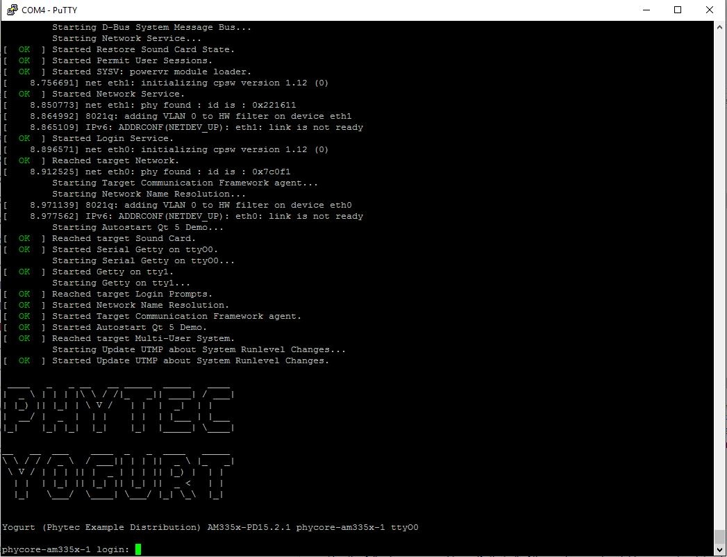
- Plug the kit-supplied 5 V power adapter into the power connector X3 on the carrier board. You will instantly see the red power LED D2 light up. You will also start to see console output on your terminal window. If everything was done correctly the board should boot completely into Linux, arriving at a root@phycore-am335x-1 prompt. The default login account is root with an empty password. Note that the first time the board is booted it will takes a little while for the SSH server to generate new keys. Subsequent boots should be faster.
Troubleshooting
Not seeing any output on the console?
- Check that you have setup the terminal software correctly per step 5.
- Flash the release images from the PHYTEC FTP by creating a bootable SD/MMC card (Creating a Bootable SD Card), then configure the board to boot from SD/MMC (Selecting Boot Modes).
When finished with the kit demo, from the Linux command line use the reboot command to restart, or the poweroff command to shutdown the system. It is safe to remove power from the kit when reboot: System halted is printed on the console.
About the Yocto BSP
The Yocto Project is a Linux embedded development environment which provides layers of meta data and tools. PHYTEC's Yocto BSPs are based on the Poky meta layer, which consists of the bitbake build tool, Linux base recipes, and various scripts to define a rudimentary linux system. The openEmbedded meta layer is also included in this BSP and is made up of a collection of meta layers which provide recipes for many software packages. The meta-phytec layer contains recipes and classes for BSPs developed by PHYTEC, such as the configuration for barebox, the kernel, and software specific to the various PHYTEC boards. The meta-yogurt layer provides additional tools as well as varous PHYTEC build images, such as phytec-qtdemo-image.
In order to help get started with PHYTEC's Yocto BSP structure, the phyLinux script can be used to obtain all the BSP sources relevant to your hardware configuration without interfacing with git or repo. Detailed information on building this BSP from source is provided following the Development Host Setup section.
Development Host Setup
Host Debian Packages
Yocto development requires certain packages to be installed. Run the following commands to ensure you have the packages installed:
sudo apt-get install gawk wget git-core diffstat unzip texinfo \
	gcc-multilib build-essential chrpath socat \
	libsdl1.2-dev xterm
The above is the recommended package installation for development on a Ubuntu 14.04 LTS Linux distribution. For a breakdown of the packages as well as a list of packages required for other Linux distributions, see the "Required Packages for the Host Development System" section in the Yocto Project Reference Manual: http://www.yoctoproject.org/docs/1.8/ref-manual/ref-manual.html#required-packages-for-the-host-development-system
Verify that the preferred shell for your Host PC is ''bash'' and not ''dash'':
sudo dpkg-reconfigure dash
# Respond "No" to the prompt asking "Install dash as /bin/sh?"
Repo Tool
Download and install the repo tool. This tool is used to obtain Yocto source from Git.
cd /opt
sudo mkdir bin

# /opt/ directory has root permission, change the permissions so your user account can access this folder. In the following replace <user> with your specific username
sudo chown -R <user>: bin

cd bin
curl http://commondatastorage.googleapis.com/git-repo-downloads/repo > ./repo
#add directory that contains repo to your path
chmod a+x repo
Add the repo directory in your PATH, using export from the command line or permanently by including it in .bashrc:
export PATH=/opt/bin/:$PATH
Git Setup
If you have not yet configured your Git environment on this machine, please execute the following commands to set your user name and email address. See here for more information on getting started with Git.
git config --global user.email "your@email.com"
git config --global user.name "Your Name"
Server Setup (Optional)
TFTP
TFTP is a "trivial" file transfer protocol used to transfer individual files across a network. Setting up a TFTP server on your Linux Host PC will allow you to exchange files with the target board. Some examples where this will be advantageous include:
- Modifying and doing development on the Linux kernel. Barebox can be configured to remotely boot the kernel so you have access to the latest build without needing to continually reflash the target board.
- Updating images from the bootloader. Transferring files over a network in Barebox is an alternative to using an SD card which eliminates some time consuming steps such as formatting an SD card.
- Individual file transfer to the root fileystem. When Linux has been fully booted you may want to copy a specific file from your Host PC to the target board (images, application executables).
Install the TFTP server on your Host PC:
sudo apt-get install tftpd-hpa
Specify a folder where the files will reside on your Host PC by replacing the folder path for ''TFTP_DIRECTORY'' with whatever folder you wish to use as your TFTP file storage location, or leave the folder as the default.
sudo gedit /etc/default/tftpd-hpa
# /etc/default/tftpd-hpa
TFTP_USERNAME="tftp"
TFTP_DIRECTORY="/var/lib/tftpboot"
TFTP_ADDRESS="0.0.0.0:69"
TFTP_OPTIONS="--secure"
If you made any changes to the settings of the TFTP server, you need to restart it for them to take effect.
sudo restart tftpd-hpa
If you would like to grant every user on the system permission to place files in the TFTP directory, use the following command, replacing ''<TFTP_DIRECTORY>'' with your chosen location.
sudo chmod ugo+rwx <TFTP_DIRECTORY>
Files in the ''<TFTP_DIRECTORY>'' on your Host PC can now be accessed from another machine on the same network such as the target board by simply using the IP address of the Host PC. Take note of this IP address, in a typical wired connection this will be ''inet addr'' listed under ''eth0''.
ifconfig
NFS
A network filesystem (NFS) server gives other systems the ability to mount a filesystem stored on the Host PC and exported over the network. Setting up an NFS server on your Linux Host PC gives you access to the target boards root filesystem which will allow you to quickly test applications and evaluate different filesystem setups for the target board. That is, the root filesystem for the board will actually be located on the remote host Linux machine. This enables easy access and modifications to the root filesystem during development.
Install the NFS server on your Host PC:
sudo apt-get install nfs-kernel-server
Exported filesystems are designated in the "/etc/exports" file and allow you to choose both the directory to be exported and many settings for accessing the exports. Below is an example for exporting a folder called "nfs_export-ex" located in a user's home directory.
sudo gedit /etc/exports
# /etc/exports
/home/<user>/nfs_export-ex *(rw,sync,no_root_squash,no_subtree_check)
The options (rw, sync, no_root_squash, no_subtree_check) for this folder are essential in setting up the NFS export correctly. For more information on additional options, refer to the man page for 'exports'.
- rw enables: read and write access when the directory is mounted
- sync: tells the file-system to handle local access calls before remote access
- no_root_squash: allows root access when mounting the file-system
- no_subtree_check: reduces the number of checks the server must make to ensure that an exported sub-directory is within an exported tree and also enables access to root files in conjunction with no_root_squash
After modifying this file, in order to mount the directories as an NFS, you must force the NFS server to export all of the directories listed in "/etc/exports".
sudo /usr/sbin/exportfs -va
Samba
Samba servers are an excellent way to access a Linux file-system on a Windows machine via a network connection. Using a Samba server, it is quick and easy to transfer files between systems.
To install a Samba server, use the following command:
sudo apt-get install samba
Before the Samba share can be mounted on another machine it's necessary to modify the configuration file to allow write access and access to home directories. Start by editing the "/etc/samba/smb.conf" file.
sudo gedit /etc/samba/smb.conf
Inside this file there are four specific things that need to be uncommented (remove the ';' at the beginning of the line) to enable the sharing of home folders and write access. Below is the section that must be modified:
#======================= Share Definitions =======================
# Un-comment the following (and tweak the other settings below to suit)
# to enable the default home directory shares. This will share each
# user's home directory as \\server\username
;[homes]
; comment = Home Directories
; browseable = yes
# By default, the home directories are exported read-only. Change the
# next parameter to 'no' if you want to be able to write to them.
; read only = no
The outcomes after the changes are made follow:
#======================= Share Definitions =======================
# Un-comment the following (and tweak the other settings below to suit)
# to enable the default home directory shares. This will share each
# user's home directory as \\server\username
[homes]
comment = Home Directories
browseable = yes
# By default, the home directories are exported read-only. Change the
# next parameter to 'no' if you want to be able to write to them.
read only = no
It might also be necessary to change the ''workgroup'' line to match the workgroup for your machine.
To apply the changes, the next step is to restart all Samba-related processes.
sudo restart smbd
sudo restart nmbd
Lastly, each user needs to have a password enabled to be able to use the Samba server. There are no rules for this password. The simplest method for choosing this password is to make it the same as the UNIX user's password, but it is not a requirement. After typing in the command below, you will be prompted to enter the password for the specified user.
sudo smbpasswd -a <user>
As mentioned in the configuration file, the samba share can be connected by accessing "\\<host machine ip>\\<user>" by either mounting a network share or using Windows explorer to navigate to it.
Building the BSP from Source
Create a directory which will house your BSP development. In this example the BSP directory is /opt/PHYTEC_BSPs/. This is not a requirement and if another location is preferred (ex. ~/PHYTEC_BSPs) feel free to modify. We recommend using /opt over your HOME directory to avoid errors attributed to ~ syntax as well as the sudo requirement for the root filesystem and automation package building. We also recommend creating a package download directory (yocto_dl) separate from the yocto tree (yocto_ti), as it makes resetting the build environment easier and subsequent build times much faster.
sudo mkdir /opt/PHYTEC_BSPs
cd /opt/

# /opt/ directory has root permission, change the permissions so your user account can access this folder. In the following replace <user> with your specific username
sudo chown -R <user>: PHYTEC_BSPs

cd PHYTEC_BSPs
mkdir yocto_ti
mkdir yocto_dl
cd yocto_ti
export YOCTO_DIR=`pwd`
At this point you will now be able to navigate to the Yocto directory using the $YOCTO_DIR environment variable.
Download the BSP Meta Layers
Download and run the init script phyLinux:
cd $YOCTO_DIR
wget ftp://ftp.phytec.de/pub/Software/Linux/Yocto/Tools/phyLinux
chmod +x phyLinux
This script will use the repo tool to manage the various git repositories used in this BSP. Repo will automatically be detected by phyLinux if it is found in the PATH. During the execution of the script, you need to choose your processor platform, BSP release and hardware. The following are the available configurations for the phyCORE-AM335x Rapid Development Kit:
- phycore-am335x-1: PCM-051-12102F0C.A1/PCM-953 (Standard Rapid Development Kit), display LCD-018 enabled by default
phycore-am335x-7: PCM-051-12102F0C.A1/PCM-953 (Standard Rapid Development Kit), display LCD-018 enabled by default + WiFi Module PCM-958
Machine configuration files 2-6 for the phycore-am335x support variants of the phyCORE-AM335x SOM used with the PCM-953 carrier board. See Here for a list of the supported boards, or contact PHYTEC support for more information.
The rest of the Quickstart assumes that the standard phycore-am335x-1 is used, although the other phyCORE-AM335x configurations may be used as well.
# You can provide the SoC platform and BSP release as arguments, and then be prompted to choose your hardware configuration:
./phyLinux init -p am335x -r PD15.2.1

# Once the source has been fetched, you will be asked to select a machine configuration. Enter "9" if using the standard phyCORE-AM335x kit (Enter "15" for the standard kit + wifi module):
***************************************************
* Please choose one of the available Machines:
*
*    1 :      beagleboneblack-1 :  Hardware Revision A5C 2GiB eMMC
*    2 : phyboard-maia-am335x-1 :  PB-00702-002, PB-00702-004
*    3 : phyboard-maia-am335x-2 :  PB-00702-003
*    4 : phyboard-maia-am335x-3 :  PB-00702-006 (with rs485)
*    5 : phyboard-wega-am335x-1 :  PB-00802-0200C PB-00802-0101C (PEB-AV-01)
*    6 : phyboard-wega-am335x-2 :  PB-00802-008 PB-00802-010 (PEB-AV-02)
*    7 : phyboard-wega-am335x-3 :  PB-00802-005.A0 PB-00802-310I.A0
*    8 : phyboard-wega-am335x-4 :  PB-00802-410C.A0
*    9 :       phycore-am335x-1 :  PCM-051-12102F0C.A1/PCM-953 (Kit)
*   10 :       phycore-am335x-2 :  1GiB RAM, 1GiB NAND variant
*   11 :       phycore-am335x-3 :  PCM-051-01041E0I.A1, PCM-051-02041E0I.A1, PCM-051-02002E0I.A1
*   12 :       phycore-am335x-4 :  PCM-051-0005160C.A1, PCM-051-0005160I.A1
*   13 :       phycore-am335x-5 :  PCM-051-00051F0I.A1
*   14 :       phycore-am335x-6 :  PCM-051-42102F0I.A0
*   15 :       phycore-am335x-7 :  PCM-051-12102F0C.A1/PCM-953 (WiFi jumpered)
*   16 :       phyflex-am335x-1 :  PFL-A-03-12113F8I.A1/PBA-B-01
*   17 :       phyflex-am335x-2 :  PFL-A-03-11041D0C.A0/PBA-B-01
*   18 :       phyflex-am335x-3 :  PFL-A-03-1005150C.A0/PBA-B-01
*   19 :       phyflex-am335x-4 :  PFL-A-03-23113F8I.A0/PBA-B-01
$ 9

# Alternately, simply run the init script and you will be prompted to choose the desired settings from a list of options
./phyLinux init
After the configuration is set up, you can view the current settings by running:
./phyLinux info
Start the Build
Run the Yocto build directory setup:
cd $YOCTO_DIR
MACHINE=phycore-am335x-1 source sources/poky/oe-init-build-env build
Add the the new download directory to $YOCTO_DIR/build/conf/local.conf:
DL_DIR ?= "/opt/PHYTEC_BSPs/yocto_dl"
The setup is complete and you now have everything to complete a build. It is suggested that you start with PHYTEC's QT5 demo image to verify functionality before building other images. Alternate images are located in various meta layers at meta*/recipes*/images/*.bb. They can be found using the command bitbake-layers show-recipes "*-image*" in $YOCTO_DIR/build/. Note that images that have been tested with this build are listed when the build directory is set up with the oe-init-build-env script.
The following will start a build from scratch including installation of the toolchain as well as barebox, Linux kernel, and root filesystem images.
cd $YOCTO_DIR/build
MACHINE=phycore-am335x-1 bitbake phytec-qt5demo-image
Built Images
All images generated by bitbake are deployed to $YOCTO_DIR/build/deploy/images/phycore-am335x-1:
- SD Image: phytec-qt5demo-image-phycore-am335x-1.sdcard
- Bootloader: barebox.bin, MLO
- Kernel: zImage
- Kernel device tree file: zImage-am335x-phycore-rdk.dtb
- Root Filesystem: phytec-qt5demo-image-phycore-am335x-1.tar.gz
Source Locations:
- Kernel: $YOCTO_DIR/build/tmp-glibc/work/phycore_am335x_1-phytec-linux-gnueabi/linux-ti/3.12.30-phy9-r0.0/git/
- The device tree file to modify within the linux kernel source is: arch/arm/boot/dts/am335x-phycore-rdk.dts and its dependencies.
- Barebox: $YOCTO_DIR/build/tmp-glibc/work/phycore_am335x_1-phytec-linux-gnueabi/barebox/2015.09.0-phy4-r6.0/git/
- MLO: $YOCTO_DIR/build/tmp-glibc/work/phycore_am335x_1-phytec-linux-gnueabi/barebox-ipl/2015.09.0-phy4-r6.0/git/
- Toolchain: $YOCTO_DIR/build/tmp-glibc/sysroots/x86_64-linux/usr/bin/arm-phytec-linux-gnueabi/arm-phytec-linux-gnueabi-
Build Time Optimizations
The build time will vary depending on the package selection and Host performance. Beyond the initial build, after making modifications to the BSP, a full build is not required. Use the following as a reference to take advantage of optimized build options and reduce the build time.
To rebuild Barebox:
bitbake barebox -f -c compile && bitbake barebox
To rebuild the Linux kernel:
bitbake linux-ti -f -c compile ; bitbake linux-ti
The Yocto project's Bitbake User Manual provides useful information regarding build options: http://www.yoctoproject.org/docs/1.8/bitbake-user-manual/bitbake-user-manual.html
Customizing the BSP
We recommend you create your own layer and make changes to the existing BSP there. This will make it easier to update the BSP. Instructions and tips on creating your own layer are available here: http://www.yoctoproject.org/docs/current/dev-manual/dev-manual.html#creating-your-own-layer
Appending Recipes
To modify an existing recipe in your own layer, use a bbappend file. The following is an example of modifying the barebox 2015.09 recipe, barebox_2015.09.0-phy4.bb, located at $YOCTO_DIR/sources/meta-phytec/recipes-bsp/barebox/
Create a ''recipes-bsp/barebox/'' directory in your own meta-layer to place the bbappend file in. Make sure that the new file matches the .bb file name exactly. Alternatively, you may use % after the underscore in place of the specific version for portability with future versions of the recipe.
mkdir $YOCTO_DIR/sources/<YOUR_META_LAYER>/recipes-bsp/barebox/
vim $YOCTO_DIR/sources/<YOUR_META_LAYER>/recipes-bsp/barebox/barebox_%.bbappend
For information on how to write a recipe, see chapter 5.3 of the Yocto Development Manual: http://www.yoctoproject.org/docs/current/dev-manual/dev-manual.html#understanding-recipe-syntax
Adding Packages to the build
There are various ways to add a package to the BSP. For example, packages and package groups can be added to image recipes. See the Yocto Development manual for how to customize an image: http://www.yoctoproject.org/docs/current/dev-manual/dev-manual.html#usingpoky-extend-customimage-imagefeatures
The following instructions demonstrate how to add a package to the local build of the BSP. First, search for the corresponding recipe and which layer the recipe is in. This link is a useful tool for doing so: http://layers.openembedded.org/layerindex/branch/dizzy/layers/.
If the package is in the meta-openembedded layer, the recipe is already available in your build tree. Add the following line to $YOCTO_DIR/build/conf/local.conf:
IMAGE_INSTALL_append = " <package>"
The leading whitespace between the " and the package name is necessary for the append command.
If you need to add a layer to the BSP, clone or extract it to the $YOCTO_DIR/sources/ directory. Then, modify $YOCTO_DIR/build/conf/bblayers.conf to include this new layer in BBLAYERS:
BBLAYERS += "${BSPDIR}/sources/<new_layer>"
Configuring the Kernel
The kernel configuration menu allows the user to adjust drivers and support included in a Linux Kernel build. run the following command from the build directory:
cd $YOCTO_DIR/build
bitbake linux-ti -c menuconfig
Then rebuild the kernel:
bitbake linux-ti -f -c compile ; bitbake linux-ti
To rebuild the root filesystem:
bitbake -f phytec-qt5demo-image
Customizing the Device Tree
The device tree is a data structure for describing hardware, and is a way of separating machine specific information from the kernel. For information on the device tree concept, devicetree.org is a good source: http://devicetree.org/Device_Tree_Usage
Device trees for PHYTEC products consist of a board DTS file, a SOM dtsi and a carrier board dtsi. The SOM dtsi includes the processor dtsi and contains definitions for all devices that are located on the SOM, such as NAND flash. Peripherals whose signals are routed through the SOM but whose hardware is located on the carrier board are defined in the carrier board dtsi, such as MMC. The board file then enables optional nodes that were defined in the dtsi files that pertain to this specific board configuration. For example, the phyCORE-AM335x SOMs may or may not have SPI NOR flash populated. If it is populated, then SPI NOR should be enabled in the board dtsi rather than the SOM dtsi.
Additionally, there are separate dtsi files for various expansion boards, such as LCD-018: am335x-phytec-lcd-018.dtsi. For more information on enabling expansions in barebox, see Expansion Board Settings.
To disable a peripheral such as SPI NOR Flash, change the status of the serial_flash node in arch/arm/boot/dts/am335x-phycore-rdk.dts from "okay" to "disabled":
&serial_flash {
	status = "disabled";
	partition@0 {
		label = "xload";
		reg = <0x0 0x20000>;
	};
...
}
The kernel source directory has very good documentation and examples on what bindings are supported for specific peripherals: Documentation/devicetree/bindings/.
Creating a Bootable SD Card
The process requires an SD card reader operational under Linux to format and access the Linux partition of the card. If you do not have SD card access under Linux then copying the bootloader and mounting the root filesystem on SD/MMC card will not be possible.
- Determine the SD card device name
The SD card device name is of the form /dev/sd[b|c|d|e]. Run the following without and with the SD card connected:
ls /dev/sd*
- The device that appeared on the call to ls with the SD card but not the call without is the SD card device.
Unmount all partitions of the SD card, using the SD card device name from Step 1:
umount /dev/sd[b|c|d|e]*
Load the sd-card image onto the SD card from the linux command line. This will format the appropriate partitions, as well as add Barebox, the kernel image, and the root filesystem to the card:
sudo dd if=phytec-qt5demo-image-phycore-am335x-1.sdcard of=/dev/sd[b|c|d|e] bs=1MB
Kernel
If modifying the kernel, remove the existing linuximage and device tree binary files:
rm /media/boot/linuximage
rm /media/boot/oftree
Load the new Linux kernel and device tree binary to the SD Card. Note that the default bootloader environment is configured to recognize "linuximage" and "oftree" as the kernel and dts respectively:
cp zImage /media/boot/linuximage; sync
cp zImage-am335x-phycore-rdk.dtb /media/boot/oftree; sync
Root Filesystem
If modifying the root filesystem, remove the existing:
sudo rm -rf /media/rootfs/*
Load the new filesystem to the SD Card:
sudo tar -zxf phytec-qt5demo-image-phycore-am335x-1.tar.gz -C /media/root/; sync
Bootloader
Remove the existing barebox and MLO images:
rm /media/boot/barebox.bin
rm /media/boot/MLO
Copy the new images to the SD Card:
cp barebox.bin /media/boot/; sync
cp MLO /media/boot/; sync
Boot Configurations
Selecting Boot Modes
The bootloader, one of the key software components included in the BSP, completes the required hardware initialization to download and run operating system images. The boot mode, selected from the S5 dipswitch on the Carrier Board, determines the location of the primary bootloader. Set the S5 dipswitch correspondingly:
NAND

NOR

SD Card

Basic Settings
After application of power, approximately three seconds are allotted for the user to hit any key which will halt autoboot and enter Barebox.

help is a useful tool in Barebox to show available commands and usage.
Expansion Board Settings
This BSP supports enabling and disabling various expansion boards that may be used along with the carrier board via the bootloader. This functionality allows for certain pin configurations to be added or removed from the device tree without needing to recompile the kernel. Please note that not all of these will be compatible with your specific board.
To view the available expansion boards:
ls /env/expansions/
.                                      ..
am335x-maia-peb-c-004                  am335x-phytec-lcd-018-pba-b-01
am335x-phytec-lcd-018-pba-c-01         am335x-phytec-lcd-018-pba-c-01-res
am335x-phytec-lcd-018-pcm-953          am335x-phytec-lcd-018-pcm-953-res
am335x-phytec-lcd-018-peb-av-02        am335x-phytec-lcd-018-peb-av-02-res
am335x-wega-peb-av-01                  am335x-wega-peb-eval-01
am335x-wlan
Enable an expansion board by adding it to /env/config-expansions:
edit /env/config-expansions
You should see something similar to the following. By default, Barebox built with the phyCORE-AM335x RDK configures the kernel to enable display LCD-018 with capacitive touchscreen:
#!/bin/sh
#use this expansion when a capacitive touchscreen is connected
. /env/expansions/am335x-phytec-lcd-018-pcm-953

#use this expansion when a resisitive touchscreen is connected
#. /env/expansions/am335x-phytec-lcd-018-pcm-953-res

#7" display
#of_display_timings -S /panel/display-timings/ETM0700G0DH6

#5.7" display
#of_display_timings -S /panel/display-timings/ETMV570G2DHU

#4.3" display
#of_display_timings -S /panel/display-timings/ETM0430G0DH6

#3.5" display
#of_display_timings -S /panel/display-timings/ETM0350G0DH6
The 3.12 kernel used by this BSP does not support device tree overlays.
Network Settings
You can check the target's network settings by running the following:
devinfo eth0
The ethaddr variable is the MAC id of the target. This is a pre-programmed value which is read from the EEPROM and matches the sticker on the SOM. To modify any of the network settings, type:
edit /env/network/eth0
You should see something similar to the following, modify the variables to specify your network configuration for ETH0:
ipaddr=###.###.###.###
netmask=###.###.###.###
gateway=###.###.###.###
serverip=###.###.###.###
- ipaddr
A dedicated IP address for the SOM. This is crucial if TFTP will be used for updating the device's images at any point.
- netmask
Netmask for the network: typically 255.255.255.0. This is only necessary if the TFTP directory is located on another network.
- gateway
Gateway IP for the network. This is only necessary if the TFTP directory is located on another network.
- serverip
IP address of the host or another machine. serverip corresponds to where the TFTP directory, if it exists, is located.
Saving Configurations
From any of the Barebox scripts, return to the Barebox prompt by pressing CTL+D to apply changes or CTL+C to cancel. To retain changes, at the Barebox prompt save the environment.
saveenv
Boot Options
The target can be booted from on-board media or from a development host via network. In our standard configuration, this BSP release loads the kernel and root filesystem from the bootsource selected in the hardware.
For booting via network, the development host is connected to the phyCORE-AM335x RDK with a serial cable and via Ethernet; the embedded board boots into the bootloader, then issues a TFTP request on the network and boots the kernel from the TFTP server on the host. Then, after decompressing the kernel into RAM and starting it, the kernel mounts its root filesystem via the NFS server on the host. This method is especially useful for development purposes as it provides a quick turnaround while testing the kernel and root filesystem.
Stand-Alone NAND Boot
To use the target stand-alone, the kernel and root filesystem have to be made persistent in the on-board media of the device. This is done by default in the kit, however if the kernel and root filesystem are not available in the on-board media or you would like to update them, refer to the Flashing Images section for information on flashing images.
When set in the dipswitch (Selecting Boot Modes section), the device is configured by default to boot the kernel and mount the root filesystem from flash. By simply resetting or power cycling the board the target will boot into Linux.
The nand boot entry can also be run from the Barebox shell:
boot nand
Remote Boot
The network-remote boot variant is intended to be used during development because of the frequent need to rebuild the Linux kernel and root filesystem. TFTP and NFS accelerate the development process. Reflashing the newest kernel and root file system to the SOM after every new build would be very cumbersome and time consuming. All that is needed is an Ethernet connection and a network aware bootloader which can fetch the kernel from a TFTP server.
Restart the board and stop autoboot to go into the Barebox shell. Edit the net boot configurations to match the NFS and TFTP set up in the Development Host Setup section.
edit env/boot/net
Modify the following variables:
- path="/mnt/tftp/<path to linuximage and oftree relative to the tftp directory setup on the host. Ex: if the tftp directory is /var/lib/tftpboot, and the files are in /var/lib/tftpboot/phytec_am335x/, then path="/mnt/tftp/phytec_am335x">"
- global.bootm.image=${path}/linuximage"
- oftree="${path}/oftree"
- nfsroot="<absolute path to NFS directory on your host machine. Ex: /home/<user>/nfs>"
Save the environment and run the command:
boot net
Stand-Alone SD/MMC Card Boot
The SD/MMC card boot variant is an alternative stand-alone boot option. All that is needed is a properly formatted (see the Creating a Bootable SD Card section of the Quickstart) SD/MMC card.
Restart the board and stop autoboot to go into the Barebox shell. Run the command:
boot mmc
Custom Boot
You may have custom boot requirements that are not covered by the four available boot files (nand, net, mmc, spi). If this is the case you can create your own custom boot entry specifying the kernel and root filesystem location.
In Barebox, create your own boot entry, for example named custom:
edit /env/boot/custom
Use the following template to specify the location of the Linux kernel and root filesystem. Please note that the text in <> such as <kernel_loc_bootm.image>, <rootfs_loc_dyn.root>, and <nfs_root_path> are intended to be replaced with user specified values.
#!/bin/sh

global.bootm.image="<kernel_loc_bootm.image>"
global.bootm.oftree="<dts_loc_bootm.oftree>"

nfsroot="<nfs_root_path>"
bootargs-ip
/env/config-expansions

global.linux.bootargs.dyn.root="<rootfs_loc_dyn.root>"
- <kernel_loc_bootm.image>
Specifies the location of the Linux kernel image- /dev/nand0.kernel.bb - To boot the Linux kernel from NAND
- ${path}/linuximage - To boot the Linux kernel via TFTP. Path relative to TFTP dir on host machine
- /boot/linuximage - To boot the Linux kernel from SD/MMC card
- <dts_loc_bootm.oftree>
Specifies the location of the device tree binary- /dev/nand0.oftree.bb - To boot the device tree binary from NAND
- ${path}/oftree - To boot the device tree binary via TFTP. Path relative to TFTP dir on host machine
- /boot/oftree - To boot the device tree binary from SD/MMC card
- <rootfs_loc_dyn.root>
Specifies the location of the root filesystem- root=ubi0:root ubi.mtd=root rootfstype=ubifs - To mount the root filesystem from NAND
- root=/dev/nfs nfsroot=$nfsroot,vers=3,udp rw consoleblank=0 - To mount the root filesystem via NFS
- root=/dev/mmcblk0p2 rootfstype=ext3 rootwait - To mount the root filesystem from SD/MMC card
- <nfs_root_path>
Only required if mounting the root filesystem from NFS. Replace with the following:- nfsroot="<absolute path to NFS directory on your host machine. Ex: /home/<user>/nfs>"
- <kernel_loc_bootm.image>
Once complete with file modifications exit the editor using CTRL+D. Save the environment:
saveenv
To run your custom boot entry from the Barebox shell:
boot custom
Default Boot
The device is configured by default to boot the kernel and mount the root filesystem from the bootsource set for Barebox in the dipswitch (Selecting Boot Modes). This default setting can be changed by adding or modifying the global.boot.default environment variable.
edit /env/init/bootsource
Comment out the if else statements which set the boot sequence depending on the Barebox bootsource, and add the global.boot.default variable to set to the desired boot source. This variable can be set to any of the entries in /env/boot. For example, to set the default boot configuration to net, global.boot.default should be set in the following way:
global.boot.default=net
Exit the editor by CTRL+D and save the environment (saveenv). On a reset or power cycle the new default boot source will take affect. Similarly it will be used in the Barebox shell when executing the following:
boot
Flashing Images
The board Development Kit is delivered with a pre-flashed bootloader. The following instructions for flashing images from TFTP or SD card will be useful if you want to:
- Flash images because NAND is empty
- Upgrade to a new release
- Use custom built images
The images to be flashed will need to be copied to the exported TFTP directory or the /boot partition of a properly formatted SD card as described in the Creating a Bootable SD Card section of the Quickstart.
After making all required connections, power on the board and enter Barebox:
- If flashing from TFTP, connect an Ethernet cable from the Ethernet connector ETH1 on the Carrier Board to your network hub, router, or switch.
- If flashing from SD card, insert a correctly formatted SD card into the SD/MMC card slot connector X20 on the Carrier Board.
- Connect a serial RS-232 cable from a free port on your Host PC to the connector X18 on the Carrier Board.
- Start your favorite terminal software (Windows: PuTTY or TeraTerm; Linux: Minicom) on your Host PC and configure it for 115200 baud, 8 data bits, no parity, and 1 stop bit (8n1).
- Power on your board by connecting the 5 V wall adapter to X3 on the Carrier Board.
- After application of power, within approximately three seconds, hit any key to halt autoboot and enter Barebox. If an Ethernet cable is connected and the network has been configured, TFTP will automount to /mnt/tftp. If an SD card was inserted and Barebox was booted from MMC, the /boot partition will automount to /boot.
If booting the bootloader from a source other than MMC, the /boot partition of the SD/MMC card will not automatically mount. To mount, execute the following commands each time you stop autoboot from Barebox or add them to /env/init/automount so this is done automatically:
mkdir -p boot
mount /dev/mmc0.0 boot
If flashing from TFTP, additional setup to configure the Barebox environment variables to meet your network environment and development host settings is required. The current network settings can be checked in /env/network/eth0.
If you need to change you network configuration, type:
edit /env/network/eth0
Edit the settings as described in the Network Settings section of the Quickstart. Save the environment and reboot the board, this will automount your tftp server at boot to /mnt/tftp.
Barebox
If you would like to upgrade, have custom Barebox requirements, or are interested in seeing the version you built in action, follow the steps below:
barebox.bin should be copied to your TFTP exported directory or the /boot partition of the SD card depending on your chosen flashing procedure.
Copy the new Barebox from your tftp-server or SD card into the module's RAM:
Method: TFTPcp /mnt/tftp/barebox.bin .
Method: SD/MMCcp /boot/barebox.bin .
Store the Barebox image into NAND Flash:
erase /dev/nand0.barebox.bb
cp barebox.bin /dev/nand0.barebox.bb
Copy the MLO into the module's RAM in the same manner as barebox.bin. To store the MLO in NAND Flash:
erase /dev/nand0.xload.bb
cp MLO /dev/nand0.xload.bb
To restore the barebox environment in NAND Flash to the default environment:
erase /dev/nand0.bareboxenv.bb
If something goes wrong and you don’t have a bootloader anymore on your module you need to boot from an SD card into Barebox (set the DIP-switch as stated in Boot Configurations) and then do the flashing. See the Creating a Bootable SD Card section of this Quickstart for a description of how to create a bootable SD card.
Kernel
Placing the kernel into NAND Flash allows booting the system without the need for the TFTP hosted kernel image. This is the most common place to put the kernel in a stand-alone application. Normally development is done using a TFTP hosted kernel image until the configuration has become more stable and is unlikely to change frequently. Once stable, the kernel image can be moved to NAND Flash. This section assumes a Linux kernel with file name linuximage is available on the exported TFTP directory or /boot partition of the SD card depending on your chosen flashing procedure.
Erase the area of NAND Flash reserved for the kernel image and device tree binary partitions:
erase /dev/nand0.kernel.bb
erase /dev/nand0.oftree.bb
Copy the Linux kernel from your tftp-server or SD card and store it into the NAND Flash:
Method: TFTPcp /mnt/tftp/linuximage /dev/nand0.kernel.bb cp /mnt/tftp/oftree /dev/nand0.oftree.bb
Method: SD/MMC
cp /boot/linuximage /dev/nand0.kernel.bb
cp /boot/oftree /dev/nand0.oftree.bb
Root Filesystem
Similar to the Linux kernel, placing the root filesystem into NAND Flash allows booting the system without the need for a remote connection to the NFS server. This section assumes a root filesystem of the form root.ubifs available on the exported TFTP directory or /boot partition of the SD card depending on your chosen flashing procedure. Note that you should not flash Linux’s root filesystem into NAND the same way as you did with Linux kernel.
Ubifs keeps erase counters within the NAND in order to be able to balance write cycles equally over all NAND sectors. So if there’s already an ubifs on your module and you want to replace it with a new one, using erase and cp will also erase these erase counters, and this should be avoided. Instead, execute the following:
ubiformat /dev/nand0.root
ubiattach /dev/nand0.root
ubimkvol /dev/nand0.root.ubi root 0
Copy the root filesystem from your tftp-server or SD card and store it into the NAND Flash:
Method: TFTPcp /mnt/tftp/phytec-qt5demo-image-phycore-am335x-1.ubifs /dev/nand0.root.ubi.root
Method: SD/MMC
cp /boot/phytec-qt5demo-image-phycore-am335x-1.ubifs /dev/nand0.root.ubi.root