1 Introduction
This document describes how to install and work with the Windows Compact 7 Board Support Package (BSP) for the phyCORE-AM3517 platform. This BSP provides a fundamental software platform for development, deployment and execution on the phyCORE-AM3517.
1.1 Quickstart Overview
The QuickStart contains instructions for:
- Host Setup
- Board Setup
- Running and Debugging Applications
- Building OS Images
- Flashing to NAND the OS (NK.bin) and bootloaders (XLDR and EBOOT)
1.2 Rapid Development Kit Documentation
This Rapid Development Kit (RDK) includes the following electronic documentation on the enlosed phyCORE-AM3517 Rapid Development Kit CD:
- The PHYTEC phyCORE-AM3517 Hardware Manual
- Controller User's Manuals and Datasheets
- This QuickStart instruction guide
1.3 Professional Support Packages Available
PHYTEC backs up our Rapid Development Kits with a Start-Up Guarantee. We invite you to make use of our free Technical Support concerning installation and setup of QuickStart demos until any kit start-up problem you might encounter is resolved. For more in-depth questions, we offer our technical support packages for purchanse. Please contact our sales team at sales@phytec.com to discuss the appropriate support option if professional support beyond installation and setup is required.
1.4 Kit Contents
The following hardware componenets are included in the phyCORE-AM3517 Windows Compact 7 Rapid Development Kit (part number KPCM-048-WinCE) and are necessary for completing the instructions in the QuickStart:
- phyCORE-AM3517 System on Module (Part # PCM-048-5566ER1l0-1A)
- phyCORE-AM3517 Carrier Board
- Bare PCB Expansion Board (PCM-988) (optional)
- AC adapter supplying 5 VDC /3.2A adapter, center positive
- Straight Ethernet cable
- Serial cable (RS-232)
- USB Standard A to mini-B cable
- SOM extraction tool
- PHYTEC Kit CD
2 System Requirements
2.1 Hardware Requirements
The following hardware components are included in the phyCORE-AM3517 Compact 7 Rapid Development Kit (part number KPCM-048-WinCE) and are necessary for completing the instructions in the QuickStart:
- phyCORE-AM3517 System on Module (Part No. PCM-048-5533ER1l0-1A)
- phyCORE-AM3517 Carrier Board (Part No. PCM-961)
- AC adapter supplying 5 VDC / 3.2A adapter, center positive
- Straight Ethernet cable
- Serial Cable (RS-232)
- USB Standard A to mini-B cable
- SOM extraction tool
2.2 Software Requirements
All software required is included in the kit and are contaned in:
- PHYTEC Kit CD
- Windows Compact 7 Evaluation Kit (includes a 90-day evaluation version of Microsoft Visual Studio 2008).
3 Host Setup
The phyCore-AM3517 (PCM-048) BSP has been developed and tested under Windows 7 x64 version with Service Pack 1. The desktop PC used for development needs to be running Windows 7 (x32 or x64) with Service Pack 1. Please also remove any previous versions of Windows CE and Visual Studio.
3.1 Installation Sequence
The following provides step-by-step instructions for installing the necessary software in the order required.
For Visual Studio 2008 and Windows Compact7, an evaluation version of each is provided as part of the RDK. These components may also be downloaded and installed via the following Microsoft site:
It is also recommended to upgrade Visual Studio 2008 from the RTM version to the SP1 version. Simply install the evaluation version and then use the following link to upgrade to the SP1 version:
3.1.1 Install Visual Studio 2008
To install Visual Studio 2008 on your desktop PC insert the DVD labeled Visual Studio 2008 Professional Edition included in this kit in your DVD ROM drive. The setup should launch automatically. If not, open a Windows Explorer window, go to your DVD drive, change to the directory VS and start setup.exe manually.
The following screen appears:

Click on Install Visual Studio 2008 and follow the instructions of the setup program.
At this point you may install the upgrade to Service Pack 1 (SP1) via the link provided in the previous section.
3.1.2 Install Windows Compact7 Platform Builder
To install the Platform Builder Plug-in for Visual Studio 2008 please insert the DVD labeled Windows Embedded Compact 7 in your DVD drive. The setup should start automatically. If not, open a Windows Explorer window, go to your DVD drive and start setup.exe manually.
When the dialog box allowing you to choose a Full Install versus Custom Install appears, chose the Custom Install as this will allow you to eliminate support for unneeded processor architectures and reduce the required disk space from 51.36GB to approximately 10 GB. De-select unwanted features and select the ARM v7 Architecture as shown in the screen below:

3.1.3 Install the phyCORE-AM3517 BSP
The phyCORE-AM3517 BSP source kit is required to be able to build and modify the OS design. Once Visual Studio 2008 and Windows Compact7 have been installed per the steps above, the source installation kit is provided as a Microsoft Installer file. The current version is labeled phyCORE-AM3517-Compact7_BSP_Source-PD11.1.0.

3.1.4 Install the phyCore-AM3517 SDK
The phyCORE-AM3517 SDK for Compact 7 is needed for writing target-oriented applications. It is installed and is integrated with Visual Studio 2008 IDE and provides a new target device for code generation. The SDK includes all headers and libraries relevant to the functionality that is included in the demo OS image.
To install the phyCORE-AM3517 SDK navigate to:
- C:\PHYTEC\phyCORE-AM3517\Compact7 BSP\SDK
and then open the file "Phytec_AM3517_sdk.msi". Accept the default installation path:
- C:\Program Files (x86)\Windows CE Tools\SDKs\Phytec_AM3517_SDK
3.1.5 Host and phyCORE-AM3517 Connections
The Host development workstation is connected to the phyCORE-AM3517 platform via both a serial cable connected to UART3 (bottom connector) and over Ethernet.
The serial connection is used for interacting with EBOOT during startup.
The serial connection settings are:
- 115200 bps, 8-bit, No parity, 1 stop-bit, No flow control
The Ethernet connection is used for downloading and debugging images and applications. This should be connected to a hub on the same sub-net as the Host workstation.
4 Board Setup
4.1 Overview
The board delivered with the Rapid Development Kit is pre-loaded in NAND with the three software components needed to boot Windows Compact 7: XLDR, EBOOT and NK.
In this state, EBOOT can be used to download new NK.bin images if the OS configuration is changed.
If for some reason either XLDR or EBOOT are corrupted and need to be replaced, this can be done via a properly formatted (bootable) SD Card as explained below.
To change between booting from NAND and booting from an SD card, switches on the carrier board are used.
4.2 Selecting Boot Modes
The boot mode is selected using switches S9 and S10 on the carrier board. This selection identifies the location from where XLDR and EBOOT are loaded for execution.
4.2.1 Booting from NAND Flash
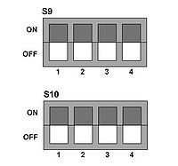
To boot (XLDR and EBOOT) from NAND, use the switch setting:
S9-1 OFF S9-2 OFF S9-3 OFF S9-4 OFF
S10-1 OFF S10-2 OFF S10-3 OFF S10-4 OFF
4.2.2 Booting from SD Memory Card
To boot (XLDR and EBOOT) from SD card, use the switch setting:
S9-1 OFF S9-2 ON S9-3 OFF S9-4 OFF
S10-1 ON S10-2 OFF S10-3 OFF S10-4 OFF
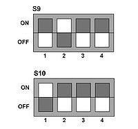
Note: Be careful when changing these switches as the S9 and S10 packages are rotated 180-degrees off of each other so the
switches will be on opposite sides for both OFF and ON and count 1-4 in different directions.
The SD card must be formatted so as to be bootable. The tool in the AM3517 platform directory, TI_SDCard_boot_utility_v1_0.exe, can be used to format and copy the MLO (XLDRSD.nb0 renamed per the Texas Instruments internal ROM boot code convention), EBOOTSD.nb0 and, optionally NK.bin.
4.3 Configuring EBOOT
EBOOT provides various functions which can be accessed upon boot by pressing the space key at startup.
- [1] Show Current Settings
- [2] Select Boot Device
- [3] Select KITL (Debug) Device
- [4] Network Settings
- [5] Flash Management
- [6] Set Device ID
- [7] Save Settings
- [8] Enable/Disable OAL Retail Messages
- [9] Select Display Resolution
- [0] Exit and Continue
4.3.1 Display Settings
By default the system is set to support a 3.5" QVGA TFT-LCD (resolution is 240x320 pixels) with integrated touch (part# KLCD-011). This is a TTL-level display.
There is also available an optional 5" VGA LVDS TFT-LCD display (resolution is 640x480 pixels).
The system also supports DVI in seven resolutions from 640x480 pixels to 1280x720 pixels.
The display chosen is selected via EBOOT menu item [9]. Be sure to save your changes by selecting EBOOT menu item [7].
5 Running and Debugging the Sample Application
PHYTEC provides you with a simple sample application to learn about downloading code onto your phyCORE-AM3517 device using Visual Studio 2008. The following sections also discuss how to modify and re-build the application, as well as how to use the Visual Studio 2008 application debugger.
5.1 Opening and Building the HelloWorld Example
The simple sample application, HelloWorld, when downloaded and executed on your device, prints the text 'Hello World' on the display of your phyCORE-AM3517.
- To open the HelloWorld project, open Visual Studio 2008 and select File->Open->Project/Solution from the menu bar.
- Browse to the folder C:\PHYTEC\phyCORE-AM3517\Compact7 BSP\Sample Applications\HelloWorld.
- Select the HelloWorld solution.
- In the Solution Platform pull-down menu make sure that the Phytec_AM3517_SDK (ARMV4I) configuration is selected and that the Phytec_AM3517_SDK ARMV7 Device is selected in the Target Device menu.
- Build the application by selecting Build->Build Solution
Note that there are two modes you can build in: 'Release' and 'Debug'. The Debug mode is useful for debugging in that it turns off compiler optimizations so essentially there is a one-to-one mapping from the source to the generated code. This way, setting a breakpoint in the source is guaranteed to translate to some line of assembly code related to that source.
The Release version is what you would normally use when deploying your application. With optimizations turned on your code will generally run faster. You can still use breakpoints and debug, but the debugger will on occassion tell you it has to move your breakpoint to the next executable instruction.
5.2 Configuring Visual Studio 2008 for Application Debugging over Ethernet
Before being able to download to the phyCORE-AM3517 target device via Visual Studio 2008's application debugger, an Ethernet connection between the Host and the target must be configured. This requires two steps:
- Boot the target using the OS, NK.bin, that is already flashed into NAND and determine the IP address of the device (which it obtains via DHCP).
After booting the target device, determine the IP address by opening a command prompt and issue the command ipconfig /all.
- Inform Visual Studio 2008 to connect to this specific IP address.
From the Visual Studio IDE main menu, select Tools->Options->Device Tools->Devices. If in the "Devices" window Phytec_AM3517_SDK_ARMV7 Device is not present, use the above pull-down menu to select. Then to the right of the "Devices" window, select "Properties". In the "Properties" windows, to the right of the "Transport" pull-down, select "Configure...". In the resulting window, select "Use Specific IP address:" and enter the target device's IP address. Select "OK" and continue.

5.3 Launching and Debugging the Demo Application
After successfully building the sample application and configuring the Ethernet connection, you can launch the application on the device simply be selecting Build->Deploy HelloWorld.
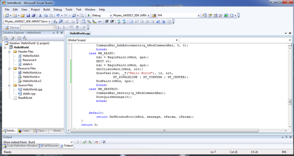
To utilize the application debugger, set a breakpoint in the code and select Debug->Start Debugging. To do this, expand the HelloWorld tree and Source Files. Double-click on HelloWorld.cpp to open the file in the source code editor.
Note: Make sure that you have selected and built the Debug version
Scroll down in the code and locate the lines:
       case WM_PAINT:
           hdc = BeginPaint(hWnd, &ps);
To the left of the second line, right-click and select Breakpoint->Insert Breakpoint.
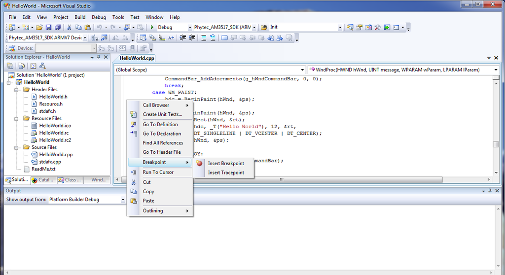
Now select Debug->Start Debugging from the menu bar. The code will be downloaded and launched, and will stop at the assigned breakpoint. You can then single-step by pressing F10.
6 Building Images
In this chapter you will learn how to use the existing sample OS design to create , download and run an OS image. You can also modify the existing sample OS design by adding or deleting components from the catalog. Finally, direction is given as to how to create a new application SDK from your modified OS design.
6.1 Building the Sample OS Design and AM3517PHYTEC BSP
The sample OS design is installed as part of the BSP installation performed in section 3.1.3. To open this OS design, open Visual Studio 2008, and from the menu bar select File->Open->Project/Solution and then browse to:
C:\WINCE700\OSDesigns\AM3517PHYTEC\AM3517PHYTEC
Then, open the OS design project AM3517Phytec.pbxml.
Again note there are two ways to build, Release and Debug. Rarely is a full Debug build of the OS required, so typically you would choose Release, in this case by selecting AM3517Phytec ARMV7 Release from the Solution Configurations pull-down menu.
Having selected this, you can build the OS image by selecting Build->Build AM3517Phytec. The full build will take 20-30 minutes depending on the OS features and the Host performance.
6.2 Creating an OS Design Using Platform Builder
Whether creating a new OS design from scratch or modifying an existing one, the primary means is by adding or deleting elements from the OS via the Catalog Items View window.
With the sample OS design opened, select the Catalog Items View. As shown below, the folders of interest are:
- AM3517Phytec->Core OS->Windows Embedded Compact
- AM3517Phytec->Third Party->BSP->AM3517Phytec:ARMV7
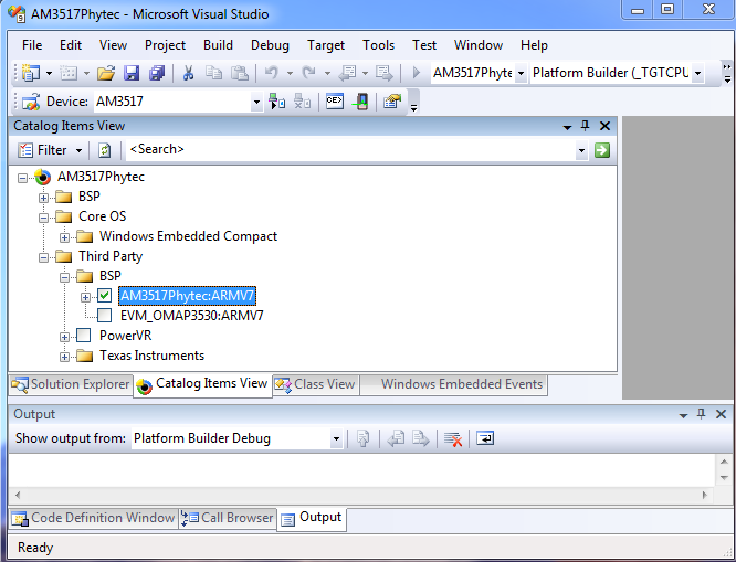
Items under Core OS are features of the OS such as ActiveSync, WordPad and USB Host.
Items under BSP are mainly the device drivers provided in the PHYTEC BSP kit.
6.2.1 Modifying the Sample OS Design
You can customize what OS and BSP components are contained in your production OS image based on the hardware and software requirements of your production device. As an example, if none of the applications you are running use managed code, you can omit Microsoft's Compact Framework support. There are other OS components that require a considerable amount of flash and RAM memory so excluding unwanted features has the added benefit of reducing your memory size requirements.
And of course not all devices will require all of the drivers supported by the BSP.
6.2.2 Creating a New SDK for an OS Design
If you modify the sample OS Design provided in the kit, you may need to create a new SDK for application development, as it provides the headers and libraries relevant to your particular OS configuration.
With your OS configuration opened in Solution Explorer and a fresh build of your OS, select Project->Add New SDK
Complete the relevant sections as needed to label and name your resulting SDK's MSI (.msi) installer file.
In Solution Explorer you will see your new SDK in the SDK's folder. Open this folder and then right-click on your SDK and select "Build". This will gather the needed components and create a new MSI.
Application developers can now use this SDK for development. They should first shut down Visual Studio 2008 and then un-install any previous SDK using the Windows Control Panel->Programs->Uninstall a program. Finally, run the new MSI file to install the new SDK.
6.3 Downloading a New OS Image
The bootloader EBOOT is capable of downloading new bootloader and OS images. It is able to communicate with Platform Builder to download and flash to NAND not only updated OS images, but also the initial program loader, XLDR, and the bootloader EBOOT.
When downloading a new OS image, one can choose whether to program the OS image into the OS partition in NAND flash, or directly to RAM. By default, OS images are built to be programmed directly to RAM. This section describes how to use EBOOT and Platform Builder to do this, using the image built in section 6.2.
6.3.1 Configuring the Bootloader to Load Image Over Ethernet
The bootloader must be configured to load an image over Ethernet. Boot the device and using the serial connection (115200 bps, 8-bit, No parity, 1 stop-bit, No flow control) enter the EBOOT configuration menu by pressing the space bar.
- Select option [2] to select the boot device
- Select option [1] for internal EMAC
- Optionally save the settings using [7]
- Select option [0] to exit and continue
EBOOT will now attempt to obtain an IP address using DHCP. After acquiring an address it will broadcast a "BOOTME" message that Platform Builder will recognize.
INFO: *** Device Name AM35x-59632 ***
InitDHCP():: Calling ProcessDHCP()
ProcessDHCP()::DHCP_INIT
Got Response from DHCP server, IP address: 192.168.3.227
ProcessDHCP()::DHCP IP Address Resolved as 192.168.3.227, netmask: 255.255.255.0
Lease time: 3600 seconds
Got Response from DHCP server, IP address: 192.168.3.227
No ARP response in 2 seconds, assuming ownership of 192.168.3.227
+EbootSendBootmeAndWaitForTftp
Sent BOOTME to 255.255.255.255
Sent BOOTME to 255.255.255.255
6.3.2 Configuring Platform Builder to Connect to Target
Platform Builder must be configured to recognize and download to the target device.
In Platform Builder, select: Target->Connectivity Options
Using the "Target Device" pull-down menu, if a device for the phyCORE-AM3517 doesn't already exist, use the "Add Device" menu item to create one:

With the Target Device selected, configure Kernel Download to be Ethernet, Kernel Transport to be Ethernet, and Kernel Debugger to be KdStub. Then select the "Settings" tab next to Kernel Download. With the target device configured in the previous section, you should see the device appear in theActive target device windows. Select it and click "Apply".

Then click "Apply" and then "Close". Then select Target->Attach Device. The download will begin and display a progress window.
7 Flashing Images to NAND
By default, OS images, NK.bin, are built to be downloaded and run from SDRAM. To be able to flash to NAND a new image, NK.bin must be built with the environment variable IMGNAND=1. This can be done in one of two ways (this assumes the OS has already been built):
1) If using the Visual Studio/Platform Builder IDE, set the IMGNAND environment variable equal to 1 (IMGNAND = 1) using
Project->Properties->Configuration Properties->Environment
And then selecting
Build->Make Run-Time Image
2) Alternatively, one can build directly from a command window by selecting
Build->Open Release Directory in Build Window
In the command window, do a "set IMGNAND = 1" and then issue a "makeimg" command.
7.1 Flashing NK.bin with Platform Builder
Once the OS image has been configured and built for flashing to NAND, follow the directions in section 6.3 - "Downloading a New OS Image". The bootloader will automatically program NK.bin into NAND flash.
7.2 Flashing NK.bin with SD Memory Card
To be able to flash NAND with a new NK.bin OS image using an SD card, the card must be formatted and marked as bootable. To do this, use the software tool in the AM3517 platform directory, TI_SDCard_boot_utility_v1_0.exe.
In addition, the following files need to be included:
1) The MLO file (a renamed version of XLDRSD.nbo) which is created as part of the build process;
2) EBOOTNAND.nbo which is a version of EBOOT with the ability to program NAND flash, but must be renamed to EBOOTSD.nb0 so XLDR can locate it.
3) NK.bin
During booting from SD card, enter the EBOOT menu by pressing the space bar during boot. From the main menu, select option "[2] - Select Boot device". Then configure the boot device to be "NK from SDCard FILE".
7.3 Flashing XLDR or EBOOT
Should it be necessary to flash to NAND either the intitial bootstrap loader, XLDR, or the bootloader, EBOOT, this can be done using a combination of an SD card containing the version of EBOOT that has the NAND flashing capability built into it (EBOOTNAND.nb0) as explained above in section 7.2,and Platform Builder.
1) Configure the system to boot from SD card (see section 4.2 - "Selecting Boot Modes");
2) Configure an SD card and place the MLO and EBOOTNAND.nb0 files on it using the tool TI_SDCard_boot_utility_v1_0.exe as described in section 4.2.2.
3) Select the image you want to download (either XLDRNAND.bin or EBOOTNAND.bin) by selecting Project->Properties->Configuration Properties->General

4) Boot the system, connect to the device, and download the image as described in section 6.3 - "Downloadiing a New OS Image".